Product Description
Product Description
structural carbon steel :45# with details in under sheet :
| Standard No. | Alloy No. | Chemical compositions(%) | ||||||
| C | Cr | Mn | Ni | P | S | Si | ||
| GB/T699-1999 | 45# | 0.42~0.50 | ≤0.25 | 0.50~0.80 | ≤0.25 | ≤0.035 | ≤0.035 | 0.17~0.37 |
| Mechanical Property |
Tensile Strength(Mpa) | Yeild Strength(Mpa) | Elongation(%) | Contraction of area Z(%) | ||||
| ≥600 | ≥355 | ≥16 | ≥40 | |||||
The correlation between properties and parameters-S45C (JIS)-SAE1045(Aisi)-SM45 of No. 45 steel(45 steel) was studied:
No. 45 steel is a carbon structural steel with 0.45% carboncontent. It is characterized by low price, good cutting performance, high hardness after quenching, good strength, toughness and wear resistance after quenching and temperingtreatment, is widely used in manufacturing structural partsand low-grade plastic mold. “45 steel” is a popular name, thesymbol is generally recorded as”45 #”. In fact GB standardsteel number is”45″, it is not a sequential number, read as”45steel” is not very accurate. Ingredient code 45 steels of similar designation are S45C (JIS) and 1045(Aisi) . In addition, ourcountry metallurgical technology standard has SM45 brandnumber to express the plastic mold use specially. Comparedwith 45 steel, SM45 has lower phosphorus and sulfur contentand better steel purity.
| Standards | YB/T 094 | AISI | JIS G4051 |
| Alloy No. | SM45 | 1045 | S45C |
| C | 0.42-0.48 | 0.43-0.50 | 0.42-0.48 |
| Si | 0.17-0.37 | 0.15-0.35 | |
| Mn | 0.50-0.80 | 0.60-0.90 | 0.60-0.90 |
| P | <0.030 | <0.030 | <0.030 |
| S | <0.035 | <0.035 | <0.035 |
Recommended process specification for heat treatment andhardness: quenching temperature 820 – 860″ C, water-oroil-cooled, hardness 250 HRC. Recommended tempering pro-cess specifcation: tempering temperature is 500 – 560″ C, aircooling, hardness is 25 – 33HRC. Tempering in this temperature range is the tempering treatment, Quenching and tempering make the strength, plasticity and toughness of 45 steelget a good balance, the comprehensive performance is good,can adapt to the alternating load environment. After quench-ing and tempering, the surface hardness of 45 steel is low anddoes not wear well. So commonly used quenching and tempering + surface quenching to improve the surface hardnessof parts.
| Tempering temperature | After quenching | Unit centigrade | |||||
| 200 | 300 | 400 | 500 | 550 | 600 | ||
| Hardness HRC |
57 | 55 | 50 | 41 | 33 | 26 | 22 |
| Mechanical properties (GB/T 699-1999) | |||
| Sample size | mm | 25 | |
| Heat treatments recommended | Normalizing | ºC | 850 |
| Quenching | ºC | 840 | |
| Tempering | ºC | 600 | |
| Mechanical properties | Tensile strongth | Mpa | ≥600 |
| Strong yield | Mpa | ≥355 | |
| Elongation | Mpa | ≥16 | |
| Section shrinkago | Mpa | ≥40 | |
| Impact | Mpa | ≥39 | |
| Hardness of delivery | HB | ≤229 | |
| HB | ≤197 | ||
Main Products
Company Profile
ZheJiang Xihu (West Lake) Dis. Equipment Manufacturing Co, Ltd., located in HangZhou City, ZheJiang Province, is a steel forging manufacturing enterprise specializing in the production of forged round steel, square steel, shaft forgings, ring forgings, cylinder forgings, and forging processing, heat treatment, mechanical processing, and finished parts processing. 0.75 tons to 30 tons of ingot steel can also be supplied. The company has a strong special steel supply channel as support, especially in the special steel forgings more resource advantages, products include “chromium-nick- el-molybdenum steel, bonded steel, carbon steel, stainless steel, spring steel, bearing steel, rolls and other series.”Our company can also ensure flaw detection at all levels according to customer requirements and provide quality certification documents.
Forging Equipment
The main equipment is 2000 tons of hydraulic press, ring rolling machine, 3 tons of forging hammer, 2 tons of forging hammer, 1 ton forging hammer, 750KG forging hammer, 30T heat treatment and temper- ing furnace, lathe, sawing machine and other more than 30 sets of equipment, which can produce
forgings weighing 20Kg-20000Kg. Products are not only widely used in domestic large locomotives, coal machines, petroleum machinery, shipbuilding and other industries, but also exported to Europe, South- east Asia, and other countries and regions, forging products using advanced production technology
“high-power electric CZPT (EF)furnace external refining (LF) vacuum degassing (VD) fast forging annealing (or normalizing) turning, Ensure chemical composition and mechanical property require-ments.
FAQ
-
What is the difference between forging and casting?
Forging: It is the process of transforming a solid from 1 shape to another. Casting: It is the process of transforming a shapeless liquid metal into a solid with a shape. The so-called casting is the process of casting molten metal into a model to obtain a casting. The casting profession focuses on the metal melting process and the control of processes during the casting process. Forging is a plastic forming process in the solid state, which can be divided into hot processing and cold processing. Forgings include extrusion, drawing, roughening, punching, and so on. Casting is a solid liquid solid process, while forging is a solid to solid process where a solid can change its shape into another shape at high temperatures. There are still differences in the shape process and process of the two.
-
How to choose high-quality forgings?
In the quality inspection of forgings, there are mainly external observation methods and internal inspection methods. The appearance method, as the name suggests, is to observe the appearance of the product, such as the shape, geometric dimensions, surface condition, etc. of the forging, in order to understand whether it meets the standards and whether there are external defects. Specifically, it is to check whether the external dimensions of the forging meet the specifications and whether there are defects on the surface, such as cracks, wrinkles, bubbles, indentations, pits, impurities, scratches, etc. on the surface of the forging. Internal testing mainly involves analyzing the chemical composition, macroscopic and microscopic structures, and mechanical properties of forgings. This inspection process requires the use of specialized instruments for high magnification inspection, with the aim of checking for any phenomena such as fractures and shrinkage within the forging, as well as defects such as dendrites and white spots, disordered flow lines, and throughflow. It also includes the tensile strength, ductility, hardness, plasticity, and heat resistance temperature of the forging.
-
What are the characteristics of the forging process for blank forgings?
The forging process of circular forgings mainly consists of the following processes: pier roughening, elongation, punching, and expanding. The difference between free forging and ring rolling processes is mainly in the process of expanding holes. In the production of ring forgings, free forging is usually used to expand the hole with a horse screw, while ring rolling is mainly used to expand the hole with rolling.
/* March 10, 2571 17:59:20 */!function(){function s(e,r){var a,o={};try{e&&e.split(“,”).forEach(function(e,t){e&&(a=e.match(/(.*?):(.*)$/))&&1
| Processing Object: | Metal |
|---|---|
| Molding Style: | Forging |
| Molding Technics: | Hot Forging |
| Application: | Machinery Parts |
| Material: | Steel |
| Heat Treatment: | Tempering |
| Samples: |
US$ 1100/Ton
1 Ton(Min.Order) | |
|---|
| Customization: |
Available
| Customized Request |
|---|

Where can I find information on axle load limits for various types of vehicles?
When seeking information on axle load limits for different types of vehicles, there are several reliable sources where you can find the necessary information. Here’s a detailed explanation of where you can find information on axle load limits:
1. Vehicle Owner’s Manual:
The first and most accessible source of information on axle load limits is the vehicle owner’s manual. The owner’s manual provided by the vehicle manufacturer typically includes important details about the vehicle’s specifications, including axle load limits. Look for sections related to vehicle loading, weight distribution, or axle specifications to find the recommended load limits for each axle of your specific vehicle model.
2. Government Transportation Authorities:
Government transportation authorities, such as departments of transportation or road transport authorities, often provide guidelines and regulations regarding vehicle weight limits, including axle load limits. These authorities establish and enforce weight restrictions to ensure road safety and prevent damage to infrastructure. Visit the website of your local or national transportation authority to access relevant regulations or guidelines pertaining to axle load limits for various types of vehicles.
3. Commercial Vehicle Regulations:
If you are specifically interested in axle load limits for commercial vehicles, such as trucks or buses, consult the commercial vehicle regulations applicable in your region. These regulations are established to ensure safe and efficient operation of commercial vehicles on public roads. Regulatory bodies responsible for commercial vehicle operations often provide detailed information on axle load limits, weight distribution requirements, and other related specifications.
4. Vehicle Manufacturer or Dealer:
If you require axle load limit information for a specific vehicle model or variant, contacting the vehicle manufacturer or a local authorized dealer can be helpful. They can provide accurate and up-to-date information specific to your vehicle. Provide them with the vehicle identification number (VIN) or other relevant details to ensure they can assist you accurately.
5. Online Resources and Databases:
There are online resources and databases dedicated to providing information on vehicle specifications, including axle load limits. These resources may include vehicle data websites, forums, or government databases that compile and provide access to vehicle specifications and regulatory information. Conduct an internet search using relevant keywords to find reliable online sources that offer information on axle load limits for various types of vehicles.
When seeking information on axle load limits, it’s crucial to ensure that the information you obtain is accurate, up-to-date, and applicable to your specific vehicle and jurisdiction. Regulations and load limits can vary depending on the country, region, vehicle type, and other factors. Therefore, it is advisable to consult official sources or seek professional advice to ensure compliance with applicable regulations and ensure safe and legal operation of your vehicle.

Can you recommend axle manufacturers known for durability and reliability?
When it comes to choosing axle manufacturers known for durability and reliability, there are several reputable companies in the automotive industry. While individual experiences and preferences may vary, the following axle manufacturers have a track record of producing high-quality products:
1. Dana Holding Corporation: Dana is a well-known manufacturer of axles, drivetrain components, and sealing solutions. They supply axles to various automotive manufacturers and have a reputation for producing durable and reliable products. Dana axles are commonly found in trucks, SUVs, and off-road vehicles.
2. AAM (American Axle & Manufacturing): AAM is a leading manufacturer of driveline and drivetrain components, including axles. They supply axles to both OEMs (Original Equipment Manufacturers) and the aftermarket. AAM axles are known for their durability and are often found in trucks, SUVs, and performance vehicles.
3. GKN Automotive: GKN Automotive is a global supplier of driveline systems, including axles. They have a strong reputation for producing high-quality and reliable axles for a wide range of vehicles. GKN Automotive supplies axles to various automakers and is recognized for their technological advancements in the field.
4. Meritor: Meritor is a manufacturer of axles, brakes, and other drivetrain components for commercial vehicles. They are known for their robust and reliable axle products that cater to heavy-duty applications in the commercial trucking industry.
5. Spicer (Dana Spicer): Spicer, a division of Dana Holding Corporation, specializes in manufacturing drivetrain components, including axles. Spicer axles are widely used in off-road vehicles, trucks, and SUVs. They are known for their durability and ability to withstand demanding off-road conditions.
6. Timken: Timken is a trusted manufacturer of bearings, seals, and other mechanical power transmission products. While they are primarily known for their bearings, they also produce high-quality axle components used in various applications, including automotive axles.
It’s important to note that the availability of specific axle manufacturers may vary depending on the region and the specific vehicle make and model. Additionally, different vehicles may come equipped with axles from different manufacturers as per the OEM’s selection and sourcing decisions.
When considering axle replacements or upgrades, it is advisable to consult with automotive experts, including mechanics or dealerships familiar with your vehicle, to ensure compatibility and make informed decisions based on your specific needs and requirements.
What are the signs of a worn or failing axle, and how can I troubleshoot axle issues?
Identifying the signs of a worn or failing axle is important for maintaining the safety and functionality of your vehicle. Here are some common signs to look out for and troubleshooting steps you can take to diagnose potential axle issues:
- Unusual Noises:
- Vibrations:
- Uneven Tire Wear:
- Difficulty Steering:
- Visible Damage or Leaks:
- Professional Inspection:
If you hear clunking, clicking, or grinding noises coming from the area around the wheels, it could indicate a problem with the axle. These noises may occur during acceleration, deceleration, or when turning. Troubleshoot by listening carefully to the location and timing of the noises to help pinpoint the affected axle.
A worn or failing axle can cause vibrations that can be felt through the steering wheel, floorboard, or seat. These vibrations may occur at certain speeds or during specific driving conditions. If you experience unusual vibrations, it’s important to investigate the cause, as it could be related to axle problems.
Inspect your tires for uneven wear patterns. Excessive wear on the inner or outer edges of the tires can be an indication of axle issues. Misaligned or damaged axles can cause the tires to tilt, leading to uneven tire wear. Regularly check your tires for signs of wear and take note of any abnormalities.
A worn or damaged axle can affect steering performance. If you experience difficulty in steering, such as stiffness, looseness, or a feeling of the vehicle pulling to one side, it may be due to axle problems. Pay attention to any changes in steering responsiveness and address them promptly.
Inspect the axles visually for any signs of damage or leaks. Look for cracks, bends, or visible fluid leaks around the axle boots or seals. Damaged or leaking axles can lead to lubrication loss and accelerated wear. If you notice any visible issues, it’s important to have them inspected and repaired by a qualified mechanic.
If you suspect axle issues but are unsure about the exact cause, it’s advisable to seek a professional inspection. A qualified mechanic can perform a thorough examination of the axles, suspension components, and related systems. They have the expertise and tools to diagnose axle problems accurately and recommend the appropriate repairs.
It’s important to note that troubleshooting axle issues can sometimes be challenging, as symptoms may overlap with other mechanical problems. If you’re uncertain about diagnosing or repairing axle issues on your own, it’s recommended to consult a professional mechanic. They can provide a proper diagnosis, ensure the correct repairs are performed, and help maintain the safety and performance of your vehicle.


editor by CX 2024-01-10
China supplier High Quality CV Axles for All Japanese Cars Wholesale Price Car Parts Best Supplier axle shaft
Product Description
CARS TYPES
| TOYOTA COROLLA | TOYOTA REVO | TOYOTA LEXUS | NISSAN TEANA |
| TOYOTA CAMRY | TOYOTA YARIS | TOYOTA DYNA | NISSAN SUNNY |
| TOYOTA HILUX | TOYOTA HIACE | TOYOTA ECHO | NISSAN SENTRA |
| TOYOTA LANDCRUSER | TOYOTA LANDCRUISER | TOYOTA DYNA | NISSAN ALMERA |
| TOYOTA RAV4 | TOYOTA FJ | TOYOTA PLATZ | NISSAN ALTEMA |
| TOYOTA FAN CARGO | TOYOTA SOLUNA | TOYOTA VIOS | NISSAN TEANA |
| HYUNDAI ELANTRA | HYUNDAI VERNA | HYUNDAI ACCENT | HYUNDAI SONATA |
Product Description
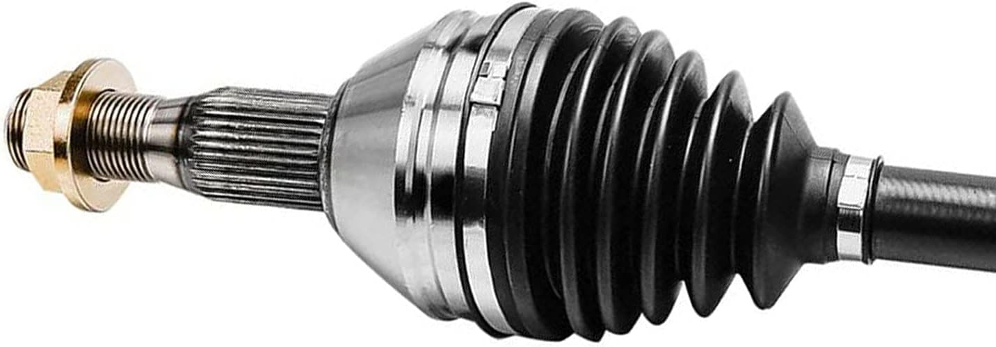
Our compay always insists high-quality standard producing and continually improve ourselves since the very beginning of company’s establishment, we always contribute to make perfect combination of equipment and technology, made the high stable quality.
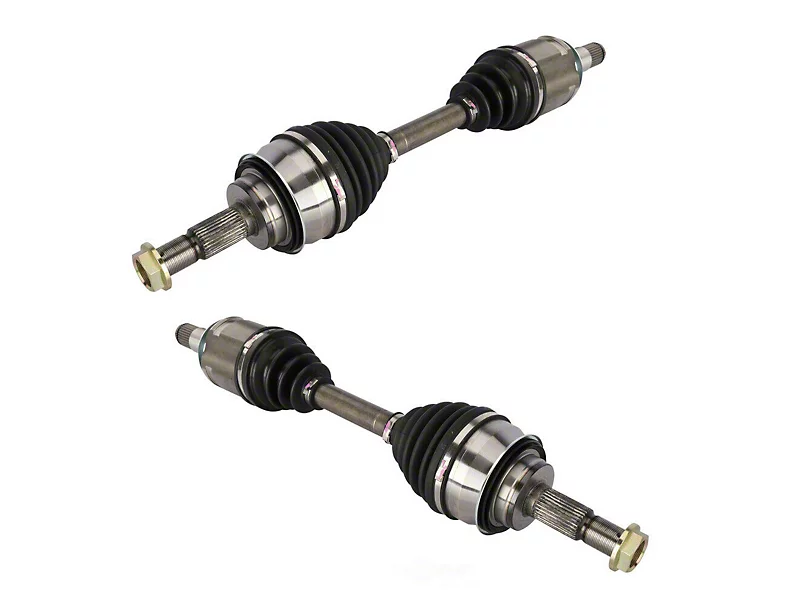
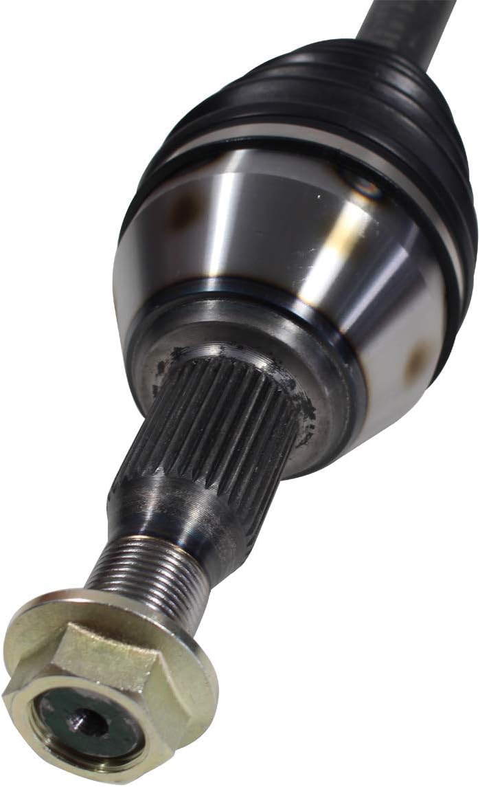
Detailed Photos
Main Products
Company Profile
ZheJiang CZPT Macinery equipments is a new developing manufacturing company with 7M$ capital. Producing Auto parts production lines. As well we have 15 years of exporting auto parts for Japanese and Korean automotive products. As after market supplies. Our main products are SHOCK ABSORBING, POWER STEERING SYSTEMS, SUSPENSION, CV AXLE, CV JONTS, and AUTO LIGHTS. We have our own brands and we do customize brand for customers requirements. Our products are produced under quality control team. Two advantage we offer; Genuine parts quality and After market price best value parts. Our products has 98% warranty for 1 year form date of use. Some items are warranty per KM 98% means we accept a claim if the damaged parts more then 2% of the quantity up to manufacturing fault for After Sales Service We have different solutions for different customers. Our company is sincerely willing to cooperate with enterprises from all over the world in order to realize a CZPT situation since the trend of economic globalization has developed with an irresistible force.
Our Factories
Packaging & Shipping
FAQ
1.Are you a factory or a trading company ?
We are a factory and trading company at the same time.
2.Where is your company located ? How can I visit there ?
Our company is located in HangZhou, all clients, from home and abroad, are warmly welcomed to visit us .
3.How about the quality of the products ?
Our products are of high quality and we have registered and reputable brands.
4.What’s the MOQ for each items ?
50 pieces.
5.Could we supply samples ?
We offer samples,but the samples should be paid.
6.What’s the delivery time ?
15-20 working days
7.What’s our shipping ways ?
We can provide different types of shipping such as sea, air, and land.
| After-sales Service: | 1 Year |
|---|---|
| Condition: | New |
| Color: | Black |
| Certification: | ISO, IATF-16949 |
| Type: | CV Axle |
| Application Brand: | Nissan, Toyota, Hyundai |
| Customization: |
Available
| Customized Request |
|---|
How do I determine the correct CV axle length for my modified or customized vehicle?
When it comes to modified or customized vehicles, determining the correct CV axle length is essential to ensure proper fitment, functionality, and optimal performance. Here’s an explanation of how you can determine the correct CV axle length for your modified or customized vehicle:
1. Consult with a Suspension Specialist or Mechanic:
It is highly recommended to consult with a suspension specialist or a qualified mechanic who has experience with modified or customized vehicles. They have the expertise and knowledge to assess your specific vehicle modifications and provide guidance on the correct CV axle length required. They can take into account factors such as suspension lift, wheel travel, geometry changes, and other modifications to determine the appropriate axle length.
2. Measure Existing Axle Length:
If you are replacing an existing CV axle and want to ensure that the new axle has the correct length, you can measure the existing axle to use as a reference. Follow these steps:
- Jack up the vehicle and secure it on jack stands.
- Remove the wheel and brake assembly to access the CV axle.
- Measure the length of the CV axle from the center of the inner CV joint to the center of the outer CV joint.
- Take note of the measurement for reference when selecting the new CV axle.
3. Consider Suspension Geometry:
When modifying or customizing a vehicle’s suspension, changes in suspension geometry can affect the required CV axle length. Factors such as suspension lift, altered suspension components, and changes in ride height need to be taken into account. Modifying the suspension can result in changes to the angle and position of the CV axles, which may require longer or shorter axles to maintain proper alignment and operation.
4. Seek Guidance from Aftermarket Manufacturers:
Aftermarket manufacturers and suppliers specializing in modified or customized vehicles may offer specific CV axles designed for certain modifications. They can provide guidance on the correct axle length based on your vehicle’s specific modifications. Research reputable aftermarket brands and reach out to their customer support or consult their product catalogs to find CV axles suitable for your modified or customized vehicle.
5. Test Fitment and Professional Installation:
Once you have determined the appropriate CV axle length based on the above considerations, it is recommended to test fit the axle before final installation. This involves temporarily fitting the axle to ensure proper alignment, engagement with the CV joints, and adequate suspension travel. If necessary, make any adjustments or seek professional assistance to ensure the correct fitment and functionality of the CV axle.
In summary, determining the correct CV axle length for a modified or customized vehicle requires consulting with suspension specialists or mechanics, measuring existing axle length as a reference, considering suspension geometry changes, seeking guidance from aftermarket manufacturers, and conducting test fitment. Proper selection and installation of the CV axle are crucial to ensure optimal performance and reliability in your modified or customized vehicle.
What is the impact of lifted or lowered suspension on CV axle angles and longevity?
Lifting or lowering a vehicle’s suspension can have a significant impact on the angles and longevity of CV axles. Here’s an explanation of how lifted or lowered suspension affects CV axle angles and longevity:
1. Lifted Suspension:
When a vehicle’s suspension is lifted, either through the use of taller springs, spacers, or suspension modifications, it can result in increased CV axle angles. The higher ride height alters the geometry of the suspension system, causing the CV axles to operate at more severe angles. This increased angle can lead to several effects:
a. Increased Wear and Stress: The higher CV axle angles in a lifted suspension setup can increase wear and stress on the CV joints and boots. The joints are forced to operate at more extreme angles, which can accelerate wear and potentially lead to premature failure. The constant articulation and operating angles can cause the CV boots to wear out faster, increasing the risk of contamination and damage to the CV joints.
b. Binding and Limited Articulation: In extreme cases, excessive lift can cause the CV axles to bind or reach their maximum operating angles, limiting the suspension’s articulation. This can result in reduced wheel travel, compromised off-road performance, and potential damage to the CV axles if the binding is severe.
c. Axle Shaft Length: In some lifted suspension setups, longer axle shafts may be required to accommodate the increased ride height. Longer axle shafts can help maintain proper CV axle angles and prevent excessive stress on the joints. It’s important to ensure that the correct length axle shafts are installed to maintain optimal CV axle operation.
2. Lowered Suspension:
Lowering a vehicle’s suspension, typically achieved through shorter springs, modified suspension components, or aftermarket kits, also affects CV axle angles and longevity. Here are some considerations:
a. Decreased CV Axle Angles: Lowering the suspension reduces the ride height of the vehicle, which can result in decreased CV axle angles. The reduced angles may alleviate some stress on the CV joints and boots, potentially leading to improved longevity.
b. Ground Clearance Concerns: Lowering a vehicle’s suspension may decrease ground clearance, making the CV axles more susceptible to potential impacts from road debris, speed bumps, or uneven surfaces. It’s important to consider the potential risks of reduced ground clearance and take appropriate measures to protect the CV axles, such as installing skid plates or ensuring proper alignment.
c. Suspension Geometry Adjustments: Lowering the suspension often requires adjustments to suspension geometry to maintain proper alignment. Incorrect suspension geometry can lead to increased CV axle angles, premature wear, and potential damage. It’s crucial to consult with a professional mechanic or suspension specialist to ensure proper suspension geometry adjustments are made when lowering the vehicle.
Regular Maintenance and Inspection:
Regardless of whether the suspension is lifted or lowered, it’s essential to regularly inspect and maintain the CV axles. This includes checking the CV boots for tears or damage, ensuring proper lubrication, and monitoring for any abnormal noises or vibrations during operation. Regular maintenance can help identify potential issues early and prevent further damage to the CV axles.
In summary, lifting or lowering a vehicle’s suspension can affect the angles and longevity of CV axles. Lifted suspensions can increase CV axle angles, leading to increased wear and stress, while lowered suspensions can potentially decrease angles but may present ground clearance concerns. Proper installation, alignment, and regular maintenance are crucial to mitigate the impact of suspension modifications on CV axle angles and longevity.
Are there aftermarket CV axles known for enhancing performance or durability?
Yes, there are aftermarket CV axles available that are known for enhancing performance or durability beyond the original equipment manufacturer (OEM) specifications. These aftermarket options often cater to specific needs, such as high-performance applications or heavy-duty usage. Here’s an explanation of some aftermarket CV axles known for enhancing performance or durability:
- Performance CV Axles: Some aftermarket manufacturers specialize in producing performance-oriented CV axles designed to handle increased power and torque. These axles may feature upgraded materials, such as stronger alloys or heat-treated components, to improve strength and durability. Performance CV axles may also incorporate design modifications to enhance torque transfer and reduce power loss, resulting in improved acceleration and responsiveness.
- Heavy-Duty CV Axles: For vehicles subjected to heavy loads or off-road conditions, there are aftermarket CV axles available that offer enhanced durability and strength. These heavy-duty axles are designed to withstand higher levels of stress and abuse compared to standard OEM axles. They often feature reinforced components, larger CV joints, and thicker shafts to handle the increased demands of towing, hauling, or traversing challenging terrains.
- Upgraded CV Axle Kits: Some aftermarket manufacturers offer complete CV axle upgrade kits that include not only the axles but also other complementary components. These kits may include upgraded CV joints, boots, clamps, and grease specifically designed for improved performance and longevity. By replacing multiple components together, these upgrade kits ensure compatibility and provide a comprehensive solution for enhancing the durability and performance of the CV axles.
- Specialty CV Axles: In certain niche markets or specific vehicle applications, there are aftermarket manufacturers that cater to unique needs. For example, there are aftermarket CV axles available for modified or custom-built vehicles that require non-standard axle lengths or angles. These specialty axles are designed to accommodate specific suspension setups or drivetrain modifications, ensuring optimal performance and durability in those specific applications.
It’s important to note that while aftermarket CV axles can offer enhancements in terms of performance or durability, there can be variations in quality and reliability among different aftermarket brands. It’s advisable to research and choose reputable aftermarket manufacturers that have a proven track record of producing reliable and high-quality products. Reading customer reviews, consulting with automotive experts, and seeking recommendations from trusted sources can help in identifying aftermarket CV axles that are known for enhancing performance or durability.
Furthermore, it’s crucial to ensure that any aftermarket CV axles chosen are compatible with your specific vehicle make, model, and drivetrain configuration. Proper installation, following manufacturer guidelines, and regular maintenance are essential to maximize the performance and durability benefits offered by aftermarket CV axles.
editor by CX 2023-12-06
China supplier Flexible Drive Shaft 3mm near me shop
Error:获取返回内容失败,
Your session has expired. Please reauthenticate.
Drive shaft type
The driveshaft transfers torque from the engine to the wheels and is responsible for the smooth running of the vehicle. Its design had to compensate for differences in length and angle. It must also ensure perfect synchronization between its joints. The drive shaft should be made of high-grade materials to achieve the best balance of stiffness and elasticity. There are three main types of drive shafts. These include: end yokes, tube yokes and tapered shafts.
tube yoke
Tube yokes are shaft assemblies that use metallic materials as the main structural component. The yoke includes a uniform, substantially uniform wall thickness, a first end and an axially extending second end. The first diameter of the drive shaft is greater than the second diameter, and the yoke further includes a pair of opposing lugs extending from the second end. These lugs have holes at the ends for attaching the axle to the vehicle.
By retrofitting the driveshaft tube end into a tube fork with seat. This valve seat transmits torque to the driveshaft tube. The fillet weld 28 enhances the torque transfer capability of the tube yoke. The yoke is usually made of aluminum alloy or metal material. It is also used to connect the drive shaft to the yoke. Various designs are possible.
The QU40866 tube yoke is used with an external snap ring type universal joint. It has a cup diameter of 1-3/16″ and an overall width of 4½”. U-bolt kits are another option. It has threaded legs and locks to help secure the yoke to the drive shaft. Some performance cars and off-road vehicles use U-bolts. Yokes must be machined to accept U-bolts, and U-bolt kits are often the preferred accessory.
The end yoke is the mechanical part that connects the drive shaft to the stub shaft. These yokes are usually designed for specific drivetrain components and can be customized to your needs. Pat’s drivetrain offers OEM replacement and custom flanged yokes.
If your tractor uses PTO components, the cross and bearing kit is the perfect tool to make the connection. Additionally, cross and bearing kits help you match the correct yoke to the shaft. When choosing a yoke, be sure to measure the outside diameter of the U-joint cap and the inside diameter of the yoke ears. After taking the measurements, consult the cross and bearing identification drawings to make sure they match.
While tube yokes are usually easy to replace, the best results come from a qualified machine shop. Dedicated driveshaft specialists can assemble and balance finished driveshafts. If you are unsure of a particular aspect, please refer to the TM3000 Driveshaft and Cardan Joint Service Manual for more information. You can also consult an excerpt from the TSB3510 manual for information on angle, vibration and runout.
The sliding fork is another important part of the drive shaft. It can bend over rough terrain, allowing the U-joint to keep spinning in tougher conditions. If the slip yoke fails, you will not be able to drive and will clang. You need to replace it as soon as possible to avoid any dangerous driving conditions. So if you notice any dings, be sure to check the yoke.
If you detect any vibrations, the drivetrain may need adjustment. It’s a simple process. First, rotate the driveshaft until you find the correct alignment between the tube yoke and the sliding yoke of the rear differential. If there is no noticeable vibration, you can wait for a while to resolve the problem. Keep in mind that it may be convenient to postpone repairs temporarily, but it may cause bigger problems later.
end yoke
If your driveshaft requires a new end yoke, CZPT has several drivetrain options. Our automotive end yoke inventory includes keyed and non-keyed options. If you need tapered or straight holes, we can also make them for you.
A U-bolt is an industrial fastener that has U-shaped threads on its legs. They are often used to join two heads back to back. These are convenient options to help keep drivetrain components in place when driving over rough terrain, and are generally compatible with a variety of models. U-bolts require a specially machined yoke to accept them, so be sure to order the correct size.
The sliding fork helps transfer power from the transfer case to the driveshaft. They slide in and out of the transfer case, allowing the u-joint to rotate. Sliding yokes or “slips” can be purchased separately. Whether you need a new one or just a few components to upgrade your driveshaft, 4 CZPT Parts will have the parts you need to repair your vehicle.
The end yoke is a necessary part of the drive shaft. It connects the drive train and the mating flange. They are also used in auxiliary power equipment. CZPT’s drivetrains are stocked with a variety of flanged yokes for OEM applications and custom builds. You can also find flanged yokes for constant velocity joints in our extensive inventory. If you don’t want to modify your existing drivetrain, we can even make a custom yoke for you.


China Good quality CV Axle 43420-33012 CZPT Camry (_V1_) 2.2 (SXV10_) 1992-2002 Drive Shaft near me supplier
Product Description
Product Description
Our compay always insists high-quality standard producing and continually improve ourselves since the very beginning of company’s establishment, we always contribute to make perfect combination of equipment and technology, made the high stable quality.
| Part Name | CV AXLE |
| Brand | AUTOJET/AAE/STOP/ as customers requirements |
| Application | Auto Transmission System |
| car maker | All AMERICAN,BIRTITSH, JAPANESS, and KOREAN |
| Placement on Vehicle | Right/ Left |
| Material | Iron/Steel |
| Warranty | 12 Months |
| Sample | Available |
| Price | 31$-79$ |
| Place of origin | Any Chinese port |
| Delivery time | 30-45 days after confirmed |
| Packing | Processional |
| MOQ | 100 PCS |
| Payment | L/C,T/T,Western Union,PayPal |
Detailed Photos
Main Products
Company Profile
ZheJiang CZPT Macinery equipments is a new developing manufacturing company. Producing Auto parts production lines. As well we have 15 years of exporting auto parts for all automotive products. As after market supplies. Our main products are SHOCK ABSORBING, POWER STEERING SYSTEMS, SUSPENSION, CV AXLE, CV JONTS, and AUTO LIGHTS. We have our own brands and we do customize brand for customers requirements. Our products are produced under quality control team. Two advantage we offer; Genuine parts quality and After market price best value parts. Our products has 98% warranty for 1 year form date of use. Some items are warranty per KM 98% means we accept a claim if the damaged parts more then 2% of the quantity up to manufacturing fault for After Sales Service We have different solutions for different customers. Our company is sincerely willing to cooperate with enterprises from all over the world in order to realize a CZPT situation since the trend of economic globalization has developed with an irresistible force.
Packaging & Shipping
FAQ
1.Are you a factory or a trading company ?
We are a factory and trading company at the same time.
2.Where is your company located ? How can I visit there ?
Our company is located in HangZhou, all clients, from home and abroad, are warmly welcomed to visit us .
3.How about the quality of the products ?
Our products are of high quality and we have registered and reputable brands.
4.What’s the MOQ for each items ?
100 pieces.
5.Could we supply samples ?
We offer samples,but the samples should be paid.
6.What’s the delivery time ?
30-45 working days after confirmed
7.What’s our shipping ways ?
We can provide different types of shipping such as sea, air, and land.
Stiffness and Torsional Vibration of Spline-Couplings
In this paper, we describe some basic characteristics of spline-coupling and examine its torsional vibration behavior. We also explore the effect of spline misalignment on rotor-spline coupling. These results will assist in the design of improved spline-coupling systems for various applications. The results are presented in Table 1.
Stiffness of spline-coupling
The stiffness of a spline-coupling is a function of the meshing force between the splines in a rotor-spline coupling system and the static vibration displacement. The meshing force depends on the coupling parameters such as the transmitting torque and the spline thickness. It increases nonlinearly with the spline thickness.
A simplified spline-coupling model can be used to evaluate the load distribution of splines under vibration and transient loads. The axle spline sleeve is displaced a z-direction and a resistance moment T is applied to the outer face of the sleeve. This simple model can satisfy a wide range of engineering requirements but may suffer from complex loading conditions. Its asymmetric clearance may affect its engagement behavior and stress distribution patterns.
The results of the simulations show that the maximum vibration acceleration in both Figures 10 and 22 was 3.03 g/s. This results indicate that a misalignment in the circumferential direction increases the instantaneous impact. Asymmetry in the coupling geometry is also found in the meshing. The right-side spline’s teeth mesh tightly while those on the left side are misaligned.
Considering the spline-coupling geometry, a semi-analytical model is used to compute stiffness. This model is a simplified form of a classical spline-coupling model, with submatrices defining the shape and stiffness of the joint. As the design clearance is a known value, the stiffness of a spline-coupling system can be analyzed using the same formula.
The results of the simulations also show that the spline-coupling system can be modeled using MASTA, a high-level commercial CAE tool for transmission analysis. In this case, the spline segments were modeled as a series of spline segments with variable stiffness, which was calculated based on the initial gap between spline teeth. Then, the spline segments were modelled as a series of splines of increasing stiffness, accounting for different manufacturing variations. The resulting analysis of the spline-coupling geometry is compared to those of the finite-element approach.
Despite the high stiffness of a spline-coupling system, the contact status of the contact surfaces often changes. In addition, spline coupling affects the lateral vibration and deformation of the rotor. However, stiffness nonlinearity is not well studied in splined rotors because of the lack of a fully analytical model.
Characteristics of spline-coupling
The study of spline-coupling involves a number of design factors. These include weight, materials, and performance requirements. Weight is particularly important in the aeronautics field. Weight is often an issue for design engineers because materials have varying dimensional stability, weight, and durability. Additionally, space constraints and other configuration restrictions may require the use of spline-couplings in certain applications.
The main parameters to consider for any spline-coupling design are the maximum principal stress, the maldistribution factor, and the maximum tooth-bearing stress. The magnitude of each of these parameters must be smaller than or equal to the external spline diameter, in order to provide stability. The outer diameter of the spline must be at least 4 inches larger than the inner diameter of the spline.
Once the physical design is validated, the spline coupling knowledge base is created. This model is pre-programmed and stores the design parameter signals, including performance and manufacturing constraints. It then compares the parameter values to the design rule signals, and constructs a geometric representation of the spline coupling. A visual model is created from the input signals, and can be manipulated by changing different parameters and specifications.
The stiffness of a spline joint is another important parameter for determining the spline-coupling stiffness. The stiffness distribution of the spline joint affects the rotor’s lateral vibration and deformation. A finite element method is a useful technique for obtaining lateral stiffness of spline joints. This method involves many mesh refinements and requires a high computational cost.
The diameter of the spline-coupling must be large enough to transmit the torque. A spline with a larger diameter may have greater torque-transmitting capacity because it has a smaller circumference. However, the larger diameter of a spline is thinner than the shaft, and the latter may be more suitable if the torque is spread over a greater number of teeth.
Spline-couplings are classified according to their tooth profile along the axial and radial directions. The radial and axial tooth profiles affect the component’s behavior and wear damage. Splines with a crowned tooth profile are prone to angular misalignment. Typically, these spline-couplings are oversized to ensure durability and safety.
Stiffness of spline-coupling in torsional vibration analysis
This article presents a general framework for the study of torsional vibration caused by the stiffness of spline-couplings in aero-engines. It is based on a previous study on spline-couplings. It is characterized by the following 3 factors: bending stiffness, total flexibility, and tangential stiffness. The first criterion is the equivalent diameter of external and internal splines. Both the spline-coupling stiffness and the displacement of splines are evaluated by using the derivative of the total flexibility.
The stiffness of a spline joint can vary based on the distribution of load along the spline. Variables affecting the stiffness of spline joints include the torque level, tooth indexing errors, and misalignment. To explore the effects of these variables, an analytical formula is developed. The method is applicable for various kinds of spline joints, such as splines with multiple components.
Despite the difficulty of calculating spline-coupling stiffness, it is possible to model the contact between the teeth of the shaft and the hub using an analytical approach. This approach helps in determining key magnitudes of coupling operation such as contact peak pressures, reaction moments, and angular momentum. This approach allows for accurate results for spline-couplings and is suitable for both torsional vibration and structural vibration analysis.
The stiffness of spline-coupling is commonly assumed to be rigid in dynamic models. However, various dynamic phenomena associated with spline joints must be captured in high-fidelity drivetrain models. To accomplish this, a general analytical stiffness formulation is proposed based on a semi-analytical spline load distribution model. The resulting stiffness matrix contains radial and tilting stiffness values as well as torsional stiffness. The analysis is further simplified with the blockwise inversion method.
It is essential to consider the torsional vibration of a power transmission system before selecting the coupling. An accurate analysis of torsional vibration is crucial for coupling safety. This article also discusses case studies of spline shaft wear and torsionally-induced failures. The discussion will conclude with the development of a robust and efficient method to simulate these problems in real-life scenarios.
Effect of spline misalignment on rotor-spline coupling
In this study, the effect of spline misalignment in rotor-spline coupling is investigated. The stability boundary and mechanism of rotor instability are analyzed. We find that the meshing force of a misaligned spline coupling increases nonlinearly with spline thickness. The results demonstrate that the misalignment is responsible for the instability of the rotor-spline coupling system.
An intentional spline misalignment is introduced to achieve an interference fit and zero backlash condition. This leads to uneven load distribution among the spline teeth. A further spline misalignment of 50um can result in rotor-spline coupling failure. The maximum tensile root stress shifted to the left under this condition.
Positive spline misalignment increases the gear mesh misalignment. Conversely, negative spline misalignment has no effect. The right-handed spline misalignment is opposite to the helix hand. The high contact area is moved from the center to the left side. In both cases, gear mesh is misaligned due to deflection and tilting of the gear under load.
This variation of the tooth surface is measured as the change in clearance in the transverse plain. The radial and axial clearance values are the same, while the difference between the 2 is less. In addition to the frictional force, the axial clearance of the splines is the same, which increases the gear mesh misalignment. Hence, the same procedure can be used to determine the frictional force of a rotor-spline coupling.
Gear mesh misalignment influences spline-rotor coupling performance. This misalignment changes the distribution of the gear mesh and alters contact and bending stresses. Therefore, it is essential to understand the effects of misalignment in spline couplings. Using a simplified system of helical gear pair, Hong et al. examined the load distribution along the tooth interface of the spline. This misalignment caused the flank contact pattern to change. The misaligned teeth exhibited deflection under load and developed a tilting moment on the gear.
The effect of spline misalignment in rotor-spline couplings is minimized by using a mechanism that reduces backlash. The mechanism comprises cooperably splined male and female members. One member is formed by 2 coaxially aligned splined segments with end surfaces shaped to engage in sliding relationship. The connecting device applies axial loads to these segments, causing them to rotate relative to 1 another.
China supplier Gjf CV Axle Assembly Drive Shaft for CZPT Corolla Carina At190 43420-20111 with high quality
Product Description
Product Description
1.We are manufacturer of cv drive shaft,cv axle, cv joint and cv boot, we have more than 20-years experience in producing and selling auto parts.
2.We have strict quality control, the quality of our products is very good.
3.We are professional in different market around the world.
4.The reviews our customers given us are very positive, we have confidence in our products.
5.OEM/ODM is available, meet your requirements well.
6.Large warehouse, huge stocks!!! friendly for those customers who want some quantity.
7.Ship products out very fastly, we have stock.
| Product Name | Drive shaft | Material | 42CrMo alloy steel |
| Car fitment | Toyota | 12 months | |
| Model | COROLLA | ZHangZhoug, China | |
| year | 1968-2571 | 4 PCS | |
| OE number | 43420-20111 | 1-7 days | |
| Yes | Brand | GJF | |
| Packing size | 0.74*0.24*0.24 | L/C,T/T,western Union,Cash,PayPal | |
| Sample service | Depends on the situation of stock | Weight | About 3.7kg-14.5kg |
Detailed Photos
Customer Review
Packaging & Shipping
FAQ
Applications of Spline Couplings
A spline coupling is a highly effective means of connecting 2 or more components. These types of couplings are very efficient, as they combine linear motion with rotation, and their efficiency makes them a desirable choice in numerous applications. Read on to learn more about the main characteristics and applications of spline couplings. You will also be able to determine the predicted operation and wear. You can easily design your own couplings by following the steps outlined below.
Optimal design
The spline coupling plays an important role in transmitting torque. It consists of a hub and a shaft with splines that are in surface contact without relative motion. Because they are connected, their angular velocity is the same. The splines can be designed with any profile that minimizes friction. Because they are in contact with each other, the load is not evenly distributed, concentrating on a small area, which can deform the hub surface.
Optimal spline coupling design takes into account several factors, including weight, material characteristics, and performance requirements. In the aeronautics industry, weight is an important design factor. S.A.E. and ANSI tables do not account for weight when calculating the performance requirements of spline couplings. Another critical factor is space. Spline couplings may need to fit in tight spaces, or they may be subject to other configuration constraints.
Optimal design of spline couplers may be characterized by an odd number of teeth. However, this is not always the case. If the external spline’s outer diameter exceeds a certain threshold, the optimal spline coupling model may not be an optimal choice for this application. To optimize a spline coupling for a specific application, the user may need to consider the sizing method that is most appropriate for their application.
Once a design is generated, the next step is to test the resulting spline coupling. The system must check for any design constraints and validate that it can be produced using modern manufacturing techniques. The resulting spline coupling model is then exported to an optimisation tool for further analysis. The method enables a designer to easily manipulate the design of a spline coupling and reduce its weight.
The spline coupling model 20 includes the major structural features of a spline coupling. A product model software program 10 stores default values for each of the spline coupling’s specifications. The resulting spline model is then calculated in accordance with the algorithm used in the present invention. The software allows the designer to enter the spline coupling’s radii, thickness, and orientation.
Characteristics
An important aspect of aero-engine splines is the load distribution among the teeth. The researchers have performed experimental tests and have analyzed the effect of lubrication conditions on the coupling behavior. Then, they devised a theoretical model using a Ruiz parameter to simulate the actual working conditions of spline couplings. This model explains the wear damage caused by the spline couplings by considering the influence of friction, misalignment, and other conditions that are relevant to the splines’ performance.
In order to design a spline coupling, the user first inputs the design criteria for sizing load carrying sections, including the external spline 40 of the spline coupling model 30. Then, the user specifies torque margin performance requirement specifications, such as the yield limit, plastic buckling, and creep buckling. The software program then automatically calculates the size and configuration of the load carrying sections and the shaft. These specifications are then entered into the model software program 10 as specification values.
Various spline coupling configuration specifications are input on the GUI screen 80. The software program 10 then generates a spline coupling model by storing default values for the various specifications. The user then can manipulate the spline coupling model by modifying its various specifications. The final result will be a computer-aided design that enables designers to optimize spline couplings based on their performance and design specifications.
The spline coupling model software program continually evaluates the validity of spline coupling models for a particular application. For example, if a user enters a data value signal corresponding to a parameter signal, the software compares the value of the signal entered to the corresponding value in the knowledge base. If the values are outside the specifications, a warning message is displayed. Once this comparison is completed, the spline coupling model software program outputs a report with the results.
Various spline coupling design factors include weight, material properties, and performance requirements. Weight is 1 of the most important design factors, particularly in the aeronautics field. ANSI and S.A.E. tables do not consider these factors when calculating the load characteristics of spline couplings. Other design requirements may also restrict the configuration of a spline coupling.
Applications
Spline couplings are a type of mechanical joint that connects 2 rotating shafts. Its 2 parts engage teeth that transfer load. Although splines are commonly over-dimensioned, they are still prone to fatigue and static behavior. These properties also make them prone to wear and tear. Therefore, proper design and selection are vital to minimize wear and tear on splines. There are many applications of spline couplings.
A key design is based on the size of the shaft being joined. This allows for the proper spacing of the keys. A novel method of hobbing allows for the formation of tapered bases without interference, and the root of the keys is concentric with the axis. These features enable for high production rates. Various applications of spline couplings can be found in various industries. To learn more, read on.
FE based methodology can predict the wear rate of spline couplings by including the evolution of the coefficient of friction. This method can predict fretting wear from simple round-on-flat geometry, and has been calibrated with experimental data. The predicted wear rate is reasonable compared to the experimental data. Friction evolution in spline couplings depends on the spline geometry. It is also crucial to consider the lubrication condition of the splines.
Using a spline coupling reduces backlash and ensures proper alignment of mated components. The shaft’s splined tooth form transfers rotation from the splined shaft to the internal splined member, which may be a gear or other rotary device. A spline coupling’s root strength and torque requirements determine the type of spline coupling that should be used.
The spline root is usually flat and has a crown on 1 side. The crowned spline has a symmetrical crown at the centerline of the face-width of the spline. As the spline length decreases toward the ends, the teeth are becoming thinner. The tooth diameter is measured in pitch. This means that the male spline has a flat root and a crowned spline.
Predictability
Spindle couplings are used in rotating machinery to connect 2 shafts. They are composed of 2 parts with teeth that engage each other and transfer load. Spline couplings are commonly over-dimensioned and are prone to static and fatigue behavior. Wear phenomena are also a common problem with splines. To address these issues, it is essential to understand the behavior and predictability of these couplings.
Dynamic behavior of spline-rotor couplings is often unclear, particularly if the system is not integrated with the rotor. For example, when a misalignment is not present, the main response frequency is 1 X-rotating speed. As the misalignment increases, the system starts to vibrate in complex ways. Furthermore, as the shaft orbits depart from the origin, the magnitudes of all the frequencies increase. Thus, research results are useful in determining proper design and troubleshooting of rotor systems.
The model of misaligned spline couplings can be obtained by analyzing the stress-compression relationships between 2 spline pairs. The meshing force model of splines is a function of the system mass, transmitting torque, and dynamic vibration displacement. This model holds when the dynamic vibration displacement is small. Besides, the CZPT stepping integration method is stable and has high efficiency.
The slip distributions are a function of the state of lubrication, coefficient of friction, and loading cycles. The predicted wear depths are well within the range of measured values. These predictions are based on the slip distributions. The methodology predicts increased wear under lightly lubricated conditions, but not under added lubrication. The lubrication condition and coefficient of friction are the key factors determining the wear behavior of splines.
China supplier GJF Drive Shaft Axle for Haima Family Mt 1998- C-Mz045A-8h with high quality
Product Description
Product Description
1.We are manufacturer of cv drive shaft,cv axle, cv joint and cv boot, we have more than 20-years experience in producing and selling auto parts.
2.We have strict quality control, the quality of our products is very good.
3.We are professional in different market around the world.
4.The reviews our customers given us are very positive, we have confidence in our products.
5.OEM/ODM is available, meet your requirements well.
6.Large warehouse, huge stocks!!! friendly for those customers who want small quantity.
7.Ship products out very fastly, we have stock.
| Product Name | Drive shaft | Material | 42CrMo alloy steel |
| Car fitment | Mitsubishi | Warranty | 12 months |
| Model | Family MT/L 1998- | Place of origin | ZHangZhoug, China |
| Brand | GJF | MOQ | 4 PCS |
| OE number | Delivery time | 1-7 days | |
| OEM/ODM | Yes | Brand | GJF |
| Packing size | 72*23.5*23.5 | Payment | L/C,T/T,western Union,Cash,PayPal |
| Sample service | Depends on the situation of stock | Weight | 6.1KG |
Detailed Photos
Customer Review
Packaging & Shipping
FAQ
Screws and Screw Shafts
A screw is a mechanical device that holds objects together. Screws are usually forged or machined. They are also used in screw jacks and press-fitted vises. Their self-locking properties make them a popular choice in many different industries. Here are some of the benefits of screws and how they work. Also read about their self-locking properties. The following information will help you choose the right screw for your application.
Machined screw shaft
A machined screw shaft can be made of various materials, depending on the application. Screw shafts can be made from stainless steel, brass, bronze, titanium, or iron. Most manufacturers use high-precision CNC machines or lathes to manufacture these products. These products come in many sizes and shapes, and they have varying applications. Different materials are used for different sizes and shapes. Here are some examples of what you can use these screws for:
Screws are widely used in many applications. One of the most common uses is in holding objects together. This type of fastener is used in screw jacks, vises, and screw presses. The thread pitch of a screw can vary. Generally, a smaller pitch results in greater mechanical advantage. Hence, a machined screw shaft should be sized appropriately. This ensures that your product will last for a long time.
A machined screw shaft should be compatible with various threading systems. In general, the ASME system is used for threaded parts. The threaded hole occupies most of the shaft. The thread of the bolt occupy either part of the shaft, or the entire one. There are also alternatives to bolts, including riveting, rolling pins, and pinned shafts. These alternatives are not widely used today, but they are useful for certain niche applications.
If you are using a ball screw, you can choose to anneal the screw shaft. To anneal the screw shaft, use a water-soaked rag as a heat barrier. You can choose from 2 different options, depending on your application. One option is to cover the screw shaft with a dust-proof enclosure. Alternatively, you can install a protective heat barrier over the screw shaft. You can also choose to cover the screw shaft with a dust-proof machine.
If you need a smaller size, you can choose a smaller screw. It may be smaller than a quarter of an inch, but it may still be compatible with another part. The smaller ones, however, will often have a corresponding mating part. These parts are typically denominated by their ANSI numerical size designation, which does not indicate threads-per-inch. There is an industry standard for screw sizes that is a little easier to understand.
Ball screw nut
When choosing a Ball screw nut for a screw shaft, it is important to consider the critical speed of the machine. This value excites the natural frequency of a screw and determines how fast it can be turned. In other words, it varies with the screw diameter and unsupported length. It also depends on the screw shaft’s diameter and end fixity. Depending on the application, the nut can be run at a maximum speed of about 80% of its theoretical critical speed.
The inner return of a ball nut is a cross-over deflector that forces the balls to climb over the crest of the screw. In 1 revolution of the screw, a ball will cross over the nut crest to return to the screw. Similarly, the outer circuit is a circular shape. Both flanges have 1 contact point on the ball shaft, and the nut is connected to the screw shaft by a screw.
The accuracy of ball screws depends on several factors, including the manufacturing precision of the ball grooves, the compactness of the assembly, and the set-up precision of the nut. Depending on the application, the lead accuracy of a ball screw nut may vary significantly. To improve lead accuracy, preloading, and lubrication are important. Ewellix ball screw assembly specialists can help you determine the best option for your application.
A ball screw nut should be preloaded prior to installation in order to achieve the expected service life. The smallest amount of preload required can reduce a ball screw’s calculated life by as much as 90 percent. Using a lubricant of a standard grade is recommended. Some lubricants contain additives. Using grease or oil in place of oil can prolong the life of the screw.
A ball screw nut is a type of threaded nut that is used in a number of different applications. It works similar to a ball bearing in that it contains hardened steel balls that move along a series of inclined races. When choosing a ball screw nut, engineers should consider the following factors: speed, life span, mounting, and lubrication. In addition, there are other considerations, such as the environment in which the screw is used.
Self-locking property of screw shaft
A self-locking screw is 1 that is capable of rotating without the use of a lock washer or bolt. This property is dependent on a number of factors, but 1 of them is the pitch angle of the thread. A screw with a small pitch angle is less likely to self-lock, while a large pitch angle is more likely to spontaneously rotate. The limiting angle of a self-locking thread can be calculated by calculating the torque Mkdw at which the screw is first released.
The pitch angle of the screw’s threads and its coefficient of friction determine the self-locking function of the screw. Other factors that affect its self-locking function include environmental conditions, high or low temperature, and vibration. Self-locking screws are often used in single-line applications and are limited by the size of their pitch. Therefore, the self-locking property of the screw shaft depends on the specific application.
The self-locking feature of a screw is an important factor. If a screw is not in a state of motion, it can be a dangerous or unusable machine. The self-locking property of a screw is critical in many applications, from corkscrews to threaded pipe joints. Screws are also used as power linkages, although their use is rarely necessary for high-power operations. In the archimedes’ screw, for example, the blades of the screw rotate around an axis. A screw conveyor uses a rotating helical chamber to move materials. A micrometer uses a precision-calibrated screw to measure length.
Self-locking screws are commonly used in lead screw technology. Their pitch and coefficient of friction are important factors in determining the self-locking property of screws. This property is advantageous in many applications because it eliminates the need for a costly brake. Its self-locking property means that the screw will be secure without requiring a special kind of force or torque. There are many other factors that contribute to the self-locking property of a screw, but this is the most common factor.
Screws with right-hand threads have threads that angle up to the right. The opposite is true for left-hand screws. While turning a screw counter-clockwise will loosen it, a right-handed person will use a right-handed thumb-up to turn it. Similarly, a left-handed person will use their thumb to turn a screw counter-clockwise. And vice versa.
Materials used to manufacture screw shaft
Many materials are commonly used to manufacture screw shafts. The most common are steel, stainless steel, brass, bronze, and titanium. These materials have advantages and disadvantages that make them good candidates for screw production. Some screw types are also made of copper to fight corrosion and ensure durability over time. Other materials include nylon, Teflon, and aluminum. Brass screws are lightweight and have aesthetic appeal. The choice of material for a screw shaft depends on the use it will be made for.
Shafts are typically produced using 3 steps. Screws are manufactured from large coils, wire, or round bar stock. After these are produced, the blanks are cut to the appropriate length and cold headed. This cold working process pressudes features into the screw head. More complicated screw shapes may require 2 heading processes to achieve the desired shape. The process is very precise and accurate, so it is an ideal choice for screw manufacturing.
The type of material used to manufacture a screw shaft is crucial for the function it will serve. The type of material chosen will depend on where the screw is being used. If the screw is for an indoor project, you can opt for a cheaper, low-tech screw. But if the screw is for an outdoor project, you’ll need to use a specific type of screw. This is because outdoor screws will be exposed to humidity and temperature changes. Some screws may even be coated with a protective coating to protect them from the elements.
Screws can also be self-threading and self-tapping. The self-threading or self-tapping screw creates a complementary helix within the material. Other screws are made with a thread which cuts into the material it fastens. Other types of screws create a helical groove on softer material to provide compression. The most common uses of a screw include holding 2 components together.
There are many types of bolts available. Some are more expensive than others, but they are generally more resistant to corrosion. They can also be made from stainless steel or aluminum. But they require high-strength materials. If you’re wondering what screws are, consider this article. There are tons of options available for screw shaft manufacturing. You’ll be surprised how versatile they can be! The choice is yours, and you can be confident that you’ll find the screw shaft that will best fit your application.
China Professional Front Right Axle Drive Shaft for Ranger Bt50 (UF9T-25-60X) near me supplier
Product Description
| Product Info | |
| Description | Front Right Axle Drive Shaft |
| OEM NO. | UF9T-25-60X |
| Size | Standard |
| Model | For Ranger BT50 |
| OEM / ODM | Available |
| Packing Details | Neutral packing or original packing or as customers’ requirements |
| Lead Time | 2-3 days in stock or 20-25 days out of Stock |
| Shipping & Payment Terms | |
| Port of Loading | HangZhou/other port as you want |
| Shipping Method | By Sea, By Air, By Carrier |
| Payment Terms | T/T, Western Union, Paypal |
What we can supply :
1. Reasonable Price and effective after -service
2. Strict Inspection System
3. delivery in time
Our advantage
1.Many years professional manufacturing supplier experience.
2.Our products range is well equipped
3. Factory price
4. Customized services
5.Sample available for quality examination
6. Small order welcome
Shipment and Payment
1: Usually we ship your order by sea or by air…
2: We do our best to ship your order within 1 week after receiving your payment
3: We’ll tell you the tracking number once your order has been sent.
4: We accept T/T Bank transfer, L/C, Western Union, Paypal.
Q & A
- How Can I Get Your catalogue?
A: Send An Enquiry To Us And Tell Us U Need Our catalogue, Our Sales Will Reply U Within 12 Hours With product catalogueQ2. Can I Get An Sample To Check Quality Before Mass Order?
A: Yes, You Can. Welcome To Place Sample Order To Check Our Quality. I Do Believe Our High Quality Products Will Bring More Orders For You From Your Clients!Q3. Any Guarantee For Your Products?
A: Our Company’s Culture Is”Quality Is Our Culture!”All Of Our Products With 12Months FREE GUARANTEE,Never Need To Worry About The After-Sale Service. We Will Always Be Here To Support Your Business!Q4. How About Your Delivery Time?
A: Generally, It Will Take 10 To 60 Days After Receiving Your Advance Payment. The Specific Delivery Time Depends
On The Items And The Quantity Of Your Order.Q5.Do You Test All Your Goods Before Delivery?
A: Yes, We Have 100 Q% Test Before Delivery.Q6. How Do You Make Our Business Long-Term And Good Relationship?
1. We Keep Good Quality And Competitive Price To Ensure Our Customers Benefit ;
2. We Respect Every Customer As Our Friend And We Sincerely Do Business And Make Friends With Them, No Matter Where They Come From.
Screw Shaft Types
A screw shaft is a cylindrical part that turns. Depending on its size, it is able to drive many different types of devices. The following information outlines the different types of screws, including their sizes, material, function, and applications. To help you select the right screw shaft, consider the following factors:
Size
A screw can come in a variety of shapes and sizes, ranging from a quarter to a quarter-inch in diameter. A screw is a cylindrical shaft with an inclined plane wrapped around it, and its main function is to fasten objects together by translating torque into a linear force. This article will discuss the dimensions of screws and how to determine the size of a screw. It is important to note that screw sizes can be large and small depending on the purpose.
The diameter of a screw is the diameter of its shaft, and it must match the inner diameter of its nuts and washers. Screws of a certain diameter are also called machine screws, and they can be larger or smaller. Screw diameters are measured on the shaft underneath the screw head. The American Society of Mechanical Engineers (ASME) standardized screw diameters in 3/50-inch to 16 (3/8-inch) inches, and more recently, sizes were added in U.S. fractions of an inch. While shaft and head diameters are standardized, screw length may vary from job to job.
In the case of the 2.3-mm screw group, the construct strength was not improved by the 1.2-mm group. The smaller screw size did not increase the strength of the construct. Further, ABS material did not improve the construct strength. Thus, the size of screw shaft is an important consideration in model design. And remember that the more complex your model is, the larger it will be. A screw of a given size will have a similar failure rate as a screw of a different diameter.
Although different screw sizes are widely used, the differences in screw size were not statistically significant. Although there are some limitations, screws of different sizes are generally sufficient for fixation of a metacarpal shaft fracture. However, further clinical studies are needed to compare screw sizes for fracture union rates. So, if you are unsure of what size of screw shaft you need for your case, make sure to check the metric chart and ensure you use the right one.
Material
The material of a screw shaft plays an important role in the overall performance of a screw. Axial and central forces act to apply torque to the screw, while external forces, such as friction, exert a bending moment. The torsional moments are reflected in the torque, and this causes the screw to rotate at a higher rate than necessary. To ensure the longevity of the screw, the material of the screw shaft should be able to handle the bending moment, while the diameter of the shaft should be small enough to avoid causing damage.
Screws are made from different metals, such as steel, brass, titanium, and bronze. Manufacturers often apply a top coating of chromium, brass, or zinc to improve corrosion resistance. Screws made of aluminum are not durable and are prone to rusting due to exposure to weather conditions. The majority of screw shafts are self-locking. They are suited for many applications, including threaded fasteners, C-clamps, and vises.
Screws that are fabricated with conical sections typically feature reduced open cross-sectional areas at the discharge point. This is a key design parameter of conical screw shafts. In fact, reductions of up to 72% are common across a variety of applications. If the screw is designed to have a hard-iron hanger bearing, it must be hardened. If the screw shaft is not hardened, it will require an additional lubricant.
Another consideration is the threads. Screw shafts are typically made of high-precision threads and ridges. These are manufactured on lathes and CNC machines. Different shapes require different materials. Materials for the screw shaft vary. There are many different sizes and shapes available, and each 1 has its own application. In addition to helical and conical screw shafts, different materials are also available. When choosing material, the best 1 depends on the application.
The life of the screw depends on its size, load, and design. In general, the material of the screw shaft, nut body, and balls and rollers determine its fatigue life. This affects the overall life of the screw. To determine whether a specific screw has a longer or shorter life, the manufacturer must consider these factors, as well as the application requirements. The material should be clean and free of imperfections. It should be smooth and free of cracks or flaking, which may result in premature failure.
Function
The function of a screw shaft is to facilitate the rotation of a screw. Screws have several thread forms, including single-start, double-start and multi-start. Each form has its own advantages and disadvantages. In this article we’ll explore each of them in detail. The function of a screw shaft can vary based on its design, but the following are common types. Here are some examples of screw shaft types and their purposes.
The screw’s torque enables it to lift objects. It can be used in conjunction with a bolt and nut to lift a load. Screws are also used to secure objects together. You can use them in screw presses, vises, and screw jacks. But their primary function is to hold objects together. Listed below are some of their main functions. When used to lift heavy loads, they can provide the required force to secure an object.
Screws can be classified into 2 types: square and round. Square threads are more efficient than round ones because they apply 0deg of angle to the nut. Square threads are also stronger than round threads and are often used in high-load applications. They’re generally cheaper to manufacture and are more difficult to break. And unlike square threads, which have a 0deg thread angle, these threads can’t be broken easily with a screwdriver.
A screw’s head is made of a series of spiral-like structures that extend from a cylindrical part to a tip. This portion of the screw is called the shank and is made of the smallest area. The shank is the portion that applies more force to the object. As the shaft extends from the head, it becomes thinner and narrow, forming a pointed tip. The head is the most important part of the screw, so it needs to be strong to perform its function.
The diameter of the screw shaft is measured in millimeters. The M8 screw has a thread pitch of 1.25 mm. Generally, the size of the screw shaft is indicated by the major and minor diameter. These dimensions are appended with a multiplication sign (M8x1).
Applications
The design of screws, including their size and shape, determines their critical rotating speeds. These speeds depend on the threaded part of the screw, the helix angle, and the geometry of the contact surfaces. When applied to a screw, these limits are referred to as “permissible speed limits.” These maximum speeds are meant for short periods of time and optimized running conditions. Continuous operation at these speeds can reduce the calculated life of a nut mechanism.
The main materials used to manufacture screws and screw shafts include steel, stainless steel, titanium, bronze, and brass. Screws may be coated for corrosion resistance, or they may be made of aluminium. Some materials can be threaded, including Teflon and nylon. Screw threads can even be molded into glass or porcelain. For the most part, steel and stainless steel are the most common materials for screw shafts. Depending on the purpose, a screw will be made of a material that is suitable for the application.
In addition to being used in fasteners, screw shafts are used in micrometers, drillers, conveyor belts, and helicopter blades. There are numerous applications of screw shafts, from weighing scales to measuring lengths. If you’re in the market for a screw, make sure to check out these applications. You’ll be happy you did! They can help you get the job done faster. So, don’t delay your next project.
If you’re interested in learning about screw sizing, then it’s important to know the axial and moment loads that your screws will experience. By following the laws of mechanics and knowing the load you can calculate the nominal life of your screw. You can also consider the effect of misalignment, uneven loading, and shocks on your screw. These will all affect the life of your screw. Then, you can select the right screw.
China supplier CV Axle for Accent III (MC) 48t Hyundai Axle Shaft wholesaler
Product Description
Product Description
Our compay always insists high-quality standard producing and continually improve ourselves since the very beginning of company’s establishment, we always contribute to make perfect combination of equipment and technology, made the high stable quality.
| Part Name | CV AXLE |
| Brand | AUTOJET/AAE/STOP/ as customers requirements |
| Application | Auto Transmission System |
| car maker | All AMERICAN,BIRTITSH, JAPANESS, and KOREAN |
| Placement on Vehicle | Right/ Left |
| Material | Iron/Steel |
| Warranty | 12 Months |
| Sample | Available |
| Price | 31$-79$ |
| Place of origin | Any Chinese port |
| Delivery time | 30-45 days after confirmed |
| Packing | Processional |
| MOQ | 100 PCS |
| Payment | L/C,T/T,Western Union,PayPal |
Detailed Photos
Main Products
Company Profile
ZheJiang CZPT Macinery equipments is a new developing manufacturing company. Producing Auto parts production lines. As well we have 15 years of exporting auto parts for all automotive products. As after market supplies. Our main products are SHOCK ABSORBING, POWER STEERING SYSTEMS, SUSPENSION, CV AXLE, CV JONTS, and AUTO LIGHTS. We have our own brands and we do customize brand for customers requirements. Our products are produced under quality control team. Two advantage we offer; Genuine parts quality and After market price best value parts. Our products has 98% warranty for 1 year form date of use. Some items are warranty per KM 98% means we accept a claim if the damaged parts more then 2% of the quantity up to manufacturing fault for After Sales Service We have different solutions for different customers. Our company is sincerely willing to cooperate with enterprises from all over the world in order to realize a CZPT situation since the trend of economic globalization has developed with an irresistible force.
Packaging & Shipping
FAQ
1.Are you a factory or a trading company ?
We are a factory and trading company at the same time.
2.Where is your company located ? How can I visit there ?
Our company is located in HangZhou, all clients, from home and abroad, are warmly welcomed to visit us .
3.How about the quality of the products ?
Our products are of high quality and we have registered and reputable brands.
4.What’s the MOQ for each items ?
100 pieces.
5.Could we supply samples ?
We offer samples,but the samples should be paid.
6.What’s the delivery time ?
30-45 working days after confirmed
7.What’s our shipping ways ?
We can provide different types of shipping such as sea, air, and land.
Screw Sizes and Their Uses
Screws have different sizes and features. This article will discuss screw sizes and their uses. There are 2 main types: right-handed and left-handed screw shafts. Each screw features a point that drills into the object. Flat tipped screws, on the other hand, need a pre-drilled hole. These screw sizes are determined by the major and minor diameters. To determine which size of screw you need, measure the diameter of the hole and the screw bolt’s thread depth.
The major diameter of a screw shaft
The major diameter of a screw shaft is the distance from the outer edge of the thread on 1 side to the tip of the other. The minor diameter is the inner smooth part of the screw shaft. The major diameter of a screw is typically between 2 and 16 inches. A screw with a pointy tip has a smaller major diameter than 1 without. In addition, a screw with a larger major diameter will have a wider head and drive.
The thread of a screw is usually characterized by its pitch and angle of engagement. The pitch is the angle formed by the helix of a thread, while the crest forms the surface of the thread corresponding to the major diameter of the screw. The pitch angle is the angle between the gear axis and the pitch surface. Screws without self-locking threads have multiple starts, or helical threads.
The pitch is a crucial component of a screw’s threading system. Pitch is the distance from a given thread point to the corresponding point of the next thread on the same shaft. The pitch line is 1 element of pitch diameter. The pitch line, or lead, is a crucial dimension for the thread of a screw, as it controls the amount of thread that will advance during a single turn.
The pitch diameter of a screw shaft
When choosing the appropriate screw, it is important to know its pitch diameter and pitch line. The pitch line designates the distance between adjacent thread sides. The pitch diameter is also known as the mean area of the screw shaft. Both of these dimensions are important when choosing the correct screw. A screw with a pitch of 1/8 will have a mechanical advantage of 6.3. For more information, consult an application engineer at Roton.
The pitch diameter of a screw shaft is measured as the distance between the crest and the root of the thread. Threads that are too long or too short will not fit together in an assembly. To measure pitch, use a measuring tool with a metric scale. If the pitch is too small, it will cause the screw to loosen or get stuck. Increasing the pitch will prevent this problem. As a result, screw diameter is critical.
The pitch diameter of a screw shaft is measured from the crest of 1 thread to the corresponding point on the next thread. Measurement is made from 1 thread to another, which is then measured using the pitch. Alternatively, the pitch diameter can be approximated by averaging the major and minor diameters. In most cases, the pitch diameter of a screw shaft is equal to the difference between the two.
The thread depth of a screw shaft
Often referred to as the major diameter, the thread depth is the outermost diameter of the screw. To measure the thread depth of a screw, use a steel rule, micrometer, or caliper. In general, the first number in the thread designation indicates the major diameter of the thread. If a section of the screw is worn, the thread depth will be smaller, and vice versa. Therefore, it is good practice to measure the section of the screw that receives the least amount of use.
In screw manufacturing, the thread depth is measured from the crest of the screw to the root. The pitch diameter is halfway between the major and minor diameters. The lead diameter represents the amount of linear distance traveled in 1 revolution. As the lead increases, the load capacity decreases. This measurement is primarily used in the construction of screws. However, it should not be used for precision machines. The thread depth of a screw shaft is essential for achieving accurate screw installation.
To measure the thread depth of a screw shaft, the manufacturer must first determine how much material the thread is exposed to. If the thread is exposed to side loads, it can cause the nut to wedge. Because the nut will be side loaded, its thread flanks will contact the nut. The less clearance between the nut and the screw, the lower the clearance between the nut and the screw. However, if the thread is centralized, there is no risk of the nut wedgeing.
The lead of a screw shaft
Pitch and lead are 2 measurements of a screw’s linear distance per turn. They’re often used interchangeably, but their definitions are not the same. The difference between them lies in the axial distance between adjacent threads. For single-start screws, the pitch is equal to the lead, while the lead of a multi-start screw is greater than the pitch. This difference is often referred to as backlash.
There are 2 ways to calculate the pitch and lead of a screw. For single-start screws, the lead and pitch are equal. Multiple-start screws, on the other hand, have multiple starts. The pitch of a multiple-start screw is the same as its lead, but with 2 or more threads running the length of the screw shaft. A square-thread screw is a better choice in applications requiring high load-bearing capacity and minimal friction losses.
The PV curve defines the safe operating limits of lead screw assemblies. It describes the inverse relationship between contact surface pressure and sliding velocity. As the load increases, the lead screw assembly must slow down in order to prevent irreversible damage from frictional heat. Furthermore, a lead screw assembly with a polymer nut must reduce rpm as the load increases. The more speed, the lower the load capacity. But, the PV factor must be below the maximum allowed value of the material used to make the screw shaft.
The thread angle of a screw shaft
The angle between the axes of a thread and the helix of a thread is called the thread angle. A unified thread has a 60-degree angle in all directions. Screws can have either a tapped hole or a captive screw. The screw pitch is measured in millimeters (mm) and is usually equal to the screw major diameter. In most cases, the thread angle will be equal to 60-degrees.
Screws with different angles have various degrees of thread. Originally, this was a problem because of the inconsistency in the threading. However, Sellers’s thread was easier to manufacture and was soon adopted as a standard throughout the United States. The United States government began to adopt this thread standard in the mid-1800s, and several influential corporations in the railroad industry endorsed it. The resulting standard is called the United States Standard thread, and it became part of the ASA’s Vol. 1 publication.
There are 2 types of screw threads: coarse and fine. The latter is easier to tighten and achieves tension at lower torques. On the other hand, the coarse thread is deeper than the fine one, making it easier to apply torque to the screw. The thread angle of a screw shaft will vary from bolt to bolt, but they will both fit in the same screw. This makes it easier to select the correct screw.
The tapped hole (or nut) into which the screw fits
A screw can be re-threaded without having to replace it altogether. The process is different than that of a standard bolt, because it requires threading and tapping. The size of a screw is typically specified by its major and minor diameters, which is the inside distance between threads. The thread pitch, which is the distance between each thread, is also specified. Thread pitch is often expressed in threads per inch.
Screws and bolts have different thread pitches. A coarse thread has fewer threads per inch and a longer distance between threads. It is therefore larger in diameter and longer than the material it is screwed into. A coarse thread is often designated with an “A” or “B” letter. The latter is generally used in smaller-scale metalworking applications. The class of threading is called a “threaded hole” and is designated by a letter.
A tapped hole is often a complication. There is a wide range of variations between the sizes of threaded holes and nut threads, so the tapped hole is a critical dimension in many applications. However, even if you choose a threaded screw that meets the requisite tolerance, there may be a mismatch in the thread pitch. This can prevent the screw from freely rotating.
China best Auto Part CV Axle 43420-06870 for CZPT Camry 2012-2018 CV Axle 48t Drive Shaft near me supplier
Product Description
Product Description
Our compay always insists high-quality standard producing and continually improve ourselves since the very beginning of company’s establishment, we always contribute to make perfect combination of equipment and technology, made the high stable quality.
| Part Name | CV AXLE |
| Brand | AUTOJET/AAE/STOP/ as customers requirements |
| Application | Auto Transmission System |
| car maker | All AMERICAN,BIRTITSH, JAPANESS, and KOREAN |
| Placement on Vehicle | Right/ Left |
| Material | Iron/Steel |
| Warranty | 12 Months |
| Sample | Available |
| Price | 31$-79$ |
| Place of origin | Any Chinese port |
| Delivery time | 30-45 days after confirmed |
| Packing | Processional |
| MOQ | 100 PCS |
| Payment | L/C,T/T,Western Union,PayPal |
Detailed Photos
Main Products
Company Profile
ZheJiang CZPT Macinery equipments is a new developing manufacturing company. Producing Auto parts production lines. As well we have 15 years of exporting auto parts for all automotive products. As after market supplies. Our main products are SHOCK ABSORBING, POWER STEERING SYSTEMS, SUSPENSION, CV AXLE, CV JONTS, and AUTO LIGHTS. We have our own brands and we do customize brand for customers requirements. Our products are produced under quality control team. Two advantage we offer; Genuine parts quality and After market price best value parts. Our products has 98% warranty for 1 year form date of use. Some items are warranty per KM 98% means we accept a claim if the damaged parts more then 2% of the quantity up to manufacturing fault for After Sales Service We have different solutions for different customers. Our company is sincerely willing to cooperate with enterprises from all over the world in order to realize a CZPT situation since the trend of economic globalization has developed with an irresistible force.
Packaging & Shipping
FAQ
1.Are you a factory or a trading company ?
We are a factory and trading company at the same time.
2.Where is your company located ? How can I visit there ?
Our company is located in HangZhou, all clients, from home and abroad, are warmly welcomed to visit us .
3.How about the quality of the products ?
Our products are of high quality and we have registered and reputable brands.
4.What’s the MOQ for each items ?
100 pieces.
5.Could we supply samples ?
We offer samples,but the samples should be paid.
6.What’s the delivery time ?
30-45 working days after confirmed
7.What’s our shipping ways ?
We can provide different types of shipping such as sea, air, and land.
Worm Shafts and Gearboxes
If you have a gearbox, you may be wondering what the best Worm Shaft is for your application. There are several things to consider, including the Concave shape, Number of threads, and Lubrication. This article will explain each factor and help you choose the right Worm Shaft for your gearbox. There are many options available on the market, so don’t hesitate to shop around. If you are new to the world of gearboxes, read on to learn more about this popular type of gearbox.
Concave shape
The geometry of a worm gear varies considerably depending on its manufacturer and its intended use. Early worms had a basic profile that resembled a screw thread and could be chased on a lathe. Later, tools with a straight sided g-angle were developed to produce threads that were parallel to the worm’s axis. Grinding was also developed to improve the finish of worm threads and minimize distortions that occur with hardening.
To select a worm with the proper geometry, the diameter of the worm gear must be in the same unit as the worm’s shaft. Once the basic profile of the worm gear is determined, the worm gear teeth can be specified. The calculation also involves an angle for the worm shaft to prevent it from overheating. The angle of the worm shaft should be as close to the vertical axis as possible.
Double-enveloping worm gears, on the other hand, do not have a throat around the worm. They are helical gears with a straight worm shaft. Since the teeth of the worm are in contact with each other, they produce significant friction. Unlike double-enveloping worm gears, non-throated worm gears are more compact and can handle smaller loads. They are also easy to manufacture.
The worm gears of different manufacturers offer many advantages. For instance, worm gears are 1 of the most efficient ways to increase torque, while lower-quality materials like bronze are difficult to lubricate. Worm gears also have a low failure rate because they allow for considerable leeway in the design process. Despite the differences between the 2 standards, the overall performance of a worm gear system is the same.
The cone-shaped worm is another type. This is a technological scheme that combines a straight worm shaft with a concave arc. The concave arc is also a useful utility model. Worms with this shape have more than 3 contacts at the same time, which means they can reduce a large diameter without excessive wear. It is also a relatively low-cost model.
Thread pattern
A good worm gear requires a perfect thread pattern. There are a few key parameters that determine how good a thread pattern is. Firstly, the threading pattern must be ACME-threaded. If this is not possible, the thread must be made with straight sides. Then, the linear pitch of the “worm” must be the same as the circular pitch of the corresponding worm wheel. In simple terms, this means the pitch of the “worm” is the same as the circular pitch of the worm wheel. A quick-change gearbox is usually used with this type of worm gear. Alternatively, lead-screw change gears are used instead of a quick-change gear box. The pitch of a worm gear equals the helix angle of a screw.
A worm gear’s axial pitch must match the circular pitch of a gear with a higher axial pitch. The circular pitch is the distance between the points of teeth on the worm, while the axial pitch is the distance between the worm’s teeth. Another factor is the worm’s lead angle. The angle between the pitch cylinder and worm shaft is called its lead angle, and the higher the lead angle, the greater the efficiency of a gear.
Worm gear tooth geometry varies depending on the manufacturer and intended use. In early worms, threading resembled the thread on a screw, and was easily chased using a lathe. Later, grinding improved worm thread finishes and minimized distortions from hardening. As a result, today, most worm gears have a thread pattern corresponding to their size. When selecting a worm gear, make sure to check for the number of threads before purchasing it.
A worm gear’s threading is crucial in its operation. Worm teeth are typically cylindrical, and are arranged in a pattern similar to screw or nut threads. Worm teeth are often formed on an axis of perpendicular compared to their parallel counterparts. Because of this, they have greater torque than their spur gear counterparts. Moreover, the gearing has a low output speed and high torque.
Number of threads
Different types of worm gears use different numbers of threads on their planetary gears. A single threaded worm gear should not be used with a double-threaded worm. A single-threaded worm gear should be used with a single-threaded worm. Single-threaded worms are more effective for speed reduction than double-threaded ones.
The number of threads on a worm’s shaft is a ratio that compares the pitch diameter and number of teeth. In general, worms have 1,2,4 threads, but some have three, five, or six. Counting thread starts can help you determine the number of threads on a worm. A single-threaded worm has fewer threads than a multiple-threaded worm, but a multi-threaded worm will have more threads than a mono-threaded planetary gear.
To measure the number of threads on a worm shaft, a small fixture with 2 ground faces is used. The worm must be removed from its housing so that the finished thread area can be inspected. After identifying the number of threads, simple measurements of the worm’s outside diameter and thread depth are taken. Once the worm has been accounted for, a cast of the tooth space is made using epoxy material. The casting is moulded between the 2 tooth flanks. The V-block fixture rests against the outside diameter of the worm.
The circular pitch of a worm and its axial pitch must match the circular pitch of a larger gear. The axial pitch of a worm is the distance between the points of the teeth on a worm’s pitch diameter. The lead of a thread is the distance a thread travels in 1 revolution. The lead angle is the tangent to the helix of a thread on a cylinder.
The worm gear’s speed transmission ratio is based on the number of threads. A worm gear with a high ratio can be easily reduced in 1 step by using a set of worm gears. However, a multi-thread worm will have more than 2 threads. The worm gear is also more efficient than single-threaded gears. And a worm gear with a high ratio will allow the motor to be used in a variety of applications.
Lubrication
The lubrication of a worm gear is particularly challenging, due to its friction and high sliding contact force. Fortunately, there are several options for lubricants, such as compounded oils. Compounded oils are mineral-based lubricants formulated with 10 percent or more fatty acid, rust and oxidation inhibitors, and other additives. This combination results in improved lubricity, reduced friction, and lower sliding wear.
When choosing a lubricant for a worm shaft, make sure the product’s viscosity is right for the type of gearing used. A low viscosity will make the gearbox difficult to actuate and rotate. Worm gears also undergo a greater sliding motion than rolling motion, so grease must be able to migrate evenly throughout the gearbox. Repeated sliding motions will push the grease away from the contact zone.
Another consideration is the backlash of the gears. Worm gears have high gear ratios, sometimes 300:1. This is important for power applications, but is at the same time inefficient. Worm gears can generate heat during the sliding motion, so a high-quality lubricant is essential. This type of lubricant will reduce heat and ensure optimal performance. The following tips will help you choose the right lubricant for your worm gear.
In low-speed applications, a grease lubricant may be sufficient. In higher-speed applications, it’s best to apply a synthetic lubricant to prevent premature failure and tooth wear. In both cases, lubricant choice depends on the tangential and rotational speed. It is important to follow manufacturer’s guidelines regarding the choice of lubricant. But remember that lubricant choice is not an easy task.
China OEM Supplier of CV Axle for Hyundai Accent III (MC) CV Axle/ Shaft 49500-1r610 Auto Parts CV Joint- 49500-1r610 with Free Design Custom
Product Description
Detailed Photos
Our compay always insists high-quality standard producing and continually improve ourselves since the very beginning of company’s establishment, we always contribute to make perfect combination of equipment and technology, made the high stable quality.
Main Products
Company Profile
ZheJiang CZPT Macinery equipments is a new developing manufacturing company with 7M$ capital. Producing Auto parts production lines. As well we have 15 years of exporting auto parts for All types of cars automotive products. As after market supplies. Our main products are SHOCK ABSORBING, POWER STEERING SYSTEMS, SUSPENSION, CV AXLE, CV JONTS, and AUTO LIGHTS. We have our own brands and we do customize brand for customers requirements. Our products are produced under quality control team. Two advantage we offer; Genuine parts quality and After market price best value parts. Our products has 98% warranty for 1 year form date of use. Some items are warranty per KM 98% means we accept a claim if the damaged parts more then 2% of the quantity up to manufacturing fault for After Sales Service We have different solutions for different customers. Our company is sincerely willing to cooperate with enterprises from all over the world in order to realize a CZPT situation since the trend of economic globalization has developed with an irresistible force.
Packaging & Shipping
FAQ
1.Are you a factory or a trading company ?
We are a factory and trading company at the same time.
2.Where is your company located ? How can I visit there ?
Our company is located in HangZhou, all clients, from home and abroad, are warmly welcomed to visit us .
3.How about the quality of the products ?
Our products are of high quality and we have registered and reputable brands.
4.What’s the MOQ for each items ?
50 pieces.
5.Could we supply samples ?
We offer samples,but the samples should be paid.
6.What’s the delivery time ?
15-20 working days
7.What’s our shipping ways ?
We can provide different types of shipping such as sea, air, and land.
Axle Spindle Types and Installation
Are you looking for a new axle spindle for your vehicle? If so, you’ve come to the right place. Learn more about their types, functions, and installation. After reading this article, you’ll be well on your way to finding your new axle spindle. Axle spindles are essential to your vehicle. There are several types and each has unique characteristics. Here’s how to choose the best 1 for your car.
Dimensions
Axle spindle dimensions are crucial for safe wheel support. This component experiences significant stress and load during bearing mounting and must provide sufficient strength. The axle spindle can be hot-forged or shaped to include an integral shoulder. The shape of the bearing stop region must be abruptly transitioned from a straight to a curved configuration. Dimensions of axle spindle vary with different materials, manufacturing techniques, and applications.
The bearing surfaces of the axle spindle are 1.376 inches across, while the bearing spacer is 1.061 inch across. The axle spindle is 1.376 inches long and includes a cotter pin and nut. Typical axle spindle dimensions are listed below. Some axles may have additional components to reduce their weight, while others may not have any. The number of axles and bearings is also important to consider when determining the dimensions of the axle.
The outside shape of the axle spindle 40 is similar to that of the prior art spindle 10. The outer wheel bearing region 44 is cylindrical with a diameter D 1 and an inner wheel bearing region 46. An axially-separating transition region 48 separates the inner bearing region 46 from the outer wheel bearing region 44. It is important to note that the internal diameter is generally slightly larger than the outer wheel bearing region 46.
Axle spindles can be integrally formed or welded to the housing or central beam. They can also be designed differently depending on the intended function. For example, the trailer axle spindle may have a circular or rectangular cross section. Once again, axle spindles are important for safety and longevity, so it is important to know their dimensions. You can also check online for the dimensions of axle spindles.
Function
Axle spindles are crucial components of a vehicle’s suspension system. They enable a vehicle to move forward, turn, brake, and accelerate. The axle also supports the wheel bearings. In addition to supporting the wheel hub, the axle spindle connects the arms of each wheel to the chassis. This piece is also known as a steering knuckle. The axle spindle’s job is to provide sufficient strength to support the axle.
The functional elements of an axle spindle are cylindrical and have a transition region and an outer surface with an irregular pattern. They have a first and a second diameter, and are shaped to form the spindle’s beam portion and spindle region. The transition region forms a pivotal connection between the axle and the suspension. It also provides the connection between the axle and the trailer. It allows a vehicle to rotate without causing excessive vibrations.
Axle spindles can be circular in structure and are similar to those of the prior art. They support wheel hub configurations. The first end of a spindle is threaded, while the second end is open. The outer wheel bearing region has an outer surface with a diameter D1, while the inner wheel bearing region 46 has a cylindrical outer surface with a diameter D2. The transition region separates the spindle from the rest of the axle.
The spindle nut retains the wheel hub on the spindle, whereas the spindle nut holds the hub assembly in place. A spindle nut retains the wheel on the spindle. A hub cap protects the locking nut assembly and lubrication area. A hub cap is also a common component of the axle. The hub cap also provides a protective shield for the spindle nut.
Steering axle spindles do not extend to the right of the oil seal. They extend from the steering kunckle, which is pivotally joined to the steering axle beam. Despite the differences in bearing seals, wheel hub mounting means, and brake assemblies, the basic spindle configuration is the same. A spindle consists of 2 axially separated bearing regions, 1 with a larger diameter than the other, with a bearing stop adjacent to the inner bearing region.
Types
The axle is the basic unit of an automobile, and it includes several components. Among these are bearings, axle housings, and wheel hubs. Bearings and axle housings take on all of the radial loads placed on them during operation. As a result, they are necessary to ensure that a vehicle is able to function at its optimum level. But if you’re not sure what these components are, they can make all the difference in your ride.
Axle type depends on a number of factors, including the amount of force produced. In some cases, the vehicle already has pre-designed axles that come in standard formats, but in other cases, a customer can order a custom-made axle for the specific needs of his vehicle. Customized axles give the vehicle operator greater control over the speed and torque of the wheels. To choose the correct axle type for your vehicle, it’s helpful to know the measurements of the axle.
Axle gear sets and lubrication passages are also different. Reverse-cut gears can’t be used in place of standard cut gears, and vice-versa. The 2 types of axle are compatible, but the spline count of the differential case must match that of the axle. It’s important to remember that a different type of axle may work with a different type of machine tool.
Different axle spindle materials have their own advantages and disadvantages. Some are more durable than others, depending on their load capacity. Disc brake hubs and axle spindles are similar to the non-braking ones, but include a rotor and a caliper yoke. The yoke design on the rotor or caliper spindle is specific for each rotor.
Bearing-type axles are the most durable. They transfer the weight of the vehicle to the axle casing. The axle housing is retained by a flange bolted to the hub, and the axle bearings are secured on the spindle by a large nut. Alternatively, axles with bearings are supported solely on the axle spindle and don’t require a hub. Floating axles are typically better for long-term operation, but may be a limited choice for vehicles.
Installation
Axle spindle installation involves tightening the axle spindle nut to retain the spacer and bearing cones in position. When properly tightened, the axle spindle nut provides the clamp force required to compress the bearing spacer and bearing cone. Preloading is an important part of axle spindle installation because it optimizes bearing life by limiting the tolerance range of end play. Here are some tips on axle spindle installation.
To start the process, you should remove the axle spindle from the vehicle. If the old spindle is not a bolt-on type, a technician will need to cut the weld that holds the axle spindle in place. Then, he or she would need to thread the new spindle back into place. The axle tube must be threaded to accept the new spindle. Once the axle spindle is properly installed, the technician will need to tighten it to the specified torque.
Once the axle spindle is installed, the technician will continue tightening the nut assembly. To ensure a tight grip, the technician will rotate the outer washer while adjusting the torque level on the axle spindle nut. If the nut is not correctly torqued, it may loosen the axle spindle. In addition, improper torque can cause excessive inboard pressure on the outer nut, which can result in over or under-compression of the bearing cone.
The second axle spindle includes an inboard bearing 54 and an outboard bearing 56. The inboard bearing has an inboard surface that abuts the shoulder 26 of the axle spindle. The outboard bearing 57 is mounted on the axle spindle near its outboard end. A bearing spacer 58 is positioned between the inboard and outboard bearings. The spacer and bearing cone group comprises the bearing cones 54 and 56.
Proper alignment of the new spindle is essential for a secure fit. Taking your trailer to a licensed repair facility for a trailer spindle installation is a good idea, as a poorly installed axle can result in improper wheel tracking and premature tire wear. A licensed trailer repair facility can do this for you without much difficulty. This way, you won’t waste your time or frustration on a DIY trailer axle replacement.