Product Description
Product Description
1.We are manufacturer of cv drive shaft,cv axle, cv joint and cv boot, we have more than 20-years experience in producing and selling auto parts.
2.We have strict quality control, the quality of our products is very good.
3.We are professional in different market around the world.
4.The reviews our customers given us are very positive, we have confidence in our products.
5.OEM/ODM is available, meet your requirements well.
6.Large warehouse, huge stocks!!! friendly for those customers who want small quantity.
7.Ship products out very fastly, we have stock.
| Product Name | Drive shaft | Material | 42CrMo alloy steel |
| Car fitment | Mitsubishi | Warranty | 12 months |
| Model | Outlander/ASX CW5 2.4/R 4WD 2008- | Place of origin | ZHangZhoug, China |
| Brand | GJF | MOQ | 4 PCS |
| OE number | 3815A066 | Delivery time | 1-7 days |
| OEM/ODM | Yes | Brand | GJF |
| Packing size | 102*23.5*23.5 | Payment | L/C,T/T,western Union,Cash,PayPal |
| Sample service | Depends on the situation of stock | Weight | 9.0KG |
Detailed Photos
Customer Review
Packaging & Shipping
FAQ
/* January 22, 2571 19:08:37 */!function(){function s(e,r){var a,o={};try{e&&e.split(“,”).forEach(function(e,t){e&&(a=e.match(/(.*?):(.*)$/))&&1
| After-sales Service: | 12 Months |
|---|---|
| Condition: | New |
| Axle Number: | 1 |
| Application: | Car |
| Certification: | ASTM, CE, DIN, ISO |
| Material: | Alloy |
| Samples: |
US$ 35/Piece
1 Piece(Min.Order) | |
|---|
| Customization: |
Available
| Customized Request |
|---|

Are there guidelines for choosing the right axle for towing heavy loads?
When it comes to towing heavy loads, selecting the appropriate axle is crucial for ensuring safe and efficient towing performance. While the specific guidelines may vary depending on the vehicle and towing requirements, there are general considerations to keep in mind when choosing the right axle. Here’s a detailed explanation of the guidelines for selecting the right axle for towing heavy loads:
Gross Axle Weight Rating (GAWR):
One of the primary factors to consider is the Gross Axle Weight Rating (GAWR) provided by the vehicle manufacturer. The GAWR specifies the maximum weight that an axle is designed to support safely. It is essential to ensure that the selected axle’s GAWR is sufficient to handle the anticipated weight of the loaded trailer and any additional cargo or passengers in the towing vehicle. Exceeding the GAWR can lead to axle failure, compromised handling, and safety risks.
Towing Capacity:
Check the towing capacity of your vehicle, which represents the maximum weight that the vehicle is rated to tow. The axle’s capacity should align with the towing capacity to ensure safe and efficient towing. Consider the type and size of the trailer you intend to tow, including its loaded weight, tongue weight, and any weight distribution considerations. The axle should be capable of handling the anticipated load without exceeding its capacity.
Matching Axle and Suspension:
The axle and suspension system work together to support the weight of the vehicle and the trailer being towed. It is important to ensure that the axle and suspension are properly matched to provide adequate support and stability. Consider the type of suspension (leaf springs, coil springs, air suspension) and the axle’s design (solid axle, independent suspension) to ensure compatibility and optimal towing performance.
Braking System:
When towing heavy loads, the braking system plays a critical role in maintaining control and safety. Ensure that the axle is equipped with appropriate brakes that can handle the increased load. Consider the type of brakes, such as electric brakes or hydraulic brakes, and their capacity to provide sufficient stopping power for the combined weight of the towing vehicle and trailer.
Weight Distribution:
Proper weight distribution is essential for safe towing. The axle should be selected based on the anticipated weight distribution between the towing vehicle and the trailer. Consider factors like tongue weight and the use of weight distribution hitches or sway control devices to ensure balanced weight distribution and optimal handling characteristics.
Consult Manufacturer Recommendations:
Always refer to the vehicle manufacturer’s recommendations, specifications, and guidelines when selecting an axle for towing heavy loads. The manufacturer’s guidelines will provide accurate and vehicle-specific information to help you make the right choice. Consult the owner’s manual or contact the manufacturer directly for any specific towing-related recommendations.
It’s important to note that towing requirements and axle specifications can vary depending on the vehicle make and model, as well as regional regulations. It is advisable to consult with automotive experts, such as mechanics or dealerships, who have expertise in towing and can provide specific recommendations based on your vehicle and towing needs.

Can you recommend axle manufacturers known for durability and reliability?
When it comes to choosing axle manufacturers known for durability and reliability, there are several reputable companies in the automotive industry. While individual experiences and preferences may vary, the following axle manufacturers have a track record of producing high-quality products:
1. Dana Holding Corporation: Dana is a well-known manufacturer of axles, drivetrain components, and sealing solutions. They supply axles to various automotive manufacturers and have a reputation for producing durable and reliable products. Dana axles are commonly found in trucks, SUVs, and off-road vehicles.
2. AAM (American Axle & Manufacturing): AAM is a leading manufacturer of driveline and drivetrain components, including axles. They supply axles to both OEMs (Original Equipment Manufacturers) and the aftermarket. AAM axles are known for their durability and are often found in trucks, SUVs, and performance vehicles.
3. GKN Automotive: GKN Automotive is a global supplier of driveline systems, including axles. They have a strong reputation for producing high-quality and reliable axles for a wide range of vehicles. GKN Automotive supplies axles to various automakers and is recognized for their technological advancements in the field.
4. Meritor: Meritor is a manufacturer of axles, brakes, and other drivetrain components for commercial vehicles. They are known for their robust and reliable axle products that cater to heavy-duty applications in the commercial trucking industry.
5. Spicer (Dana Spicer): Spicer, a division of Dana Holding Corporation, specializes in manufacturing drivetrain components, including axles. Spicer axles are widely used in off-road vehicles, trucks, and SUVs. They are known for their durability and ability to withstand demanding off-road conditions.
6. Timken: Timken is a trusted manufacturer of bearings, seals, and other mechanical power transmission products. While they are primarily known for their bearings, they also produce high-quality axle components used in various applications, including automotive axles.
It’s important to note that the availability of specific axle manufacturers may vary depending on the region and the specific vehicle make and model. Additionally, different vehicles may come equipped with axles from different manufacturers as per the OEM’s selection and sourcing decisions.
When considering axle replacements or upgrades, it is advisable to consult with automotive experts, including mechanics or dealerships familiar with your vehicle, to ensure compatibility and make informed decisions based on your specific needs and requirements.

Are there aftermarket axles available for upgrading performance in off-road vehicles?
Yes, there are aftermarket axles available for upgrading performance in off-road vehicles. Off-road enthusiasts often seek aftermarket axle options to enhance the durability, strength, and performance of their vehicles in rugged and demanding terrains. Here’s some information about aftermarket axles for off-road applications:
1. Upgraded Axle Materials:
Aftermarket axles are typically made from high-strength materials such as chromoly steel or forged alloys. These materials offer superior strength and durability compared to stock axles, making them better suited for off-road use where extreme loads, impacts, and torsional forces are encountered.
2. Increased Axle Shaft Diameter:
Some aftermarket axles feature larger diameter shafts compared to stock axles. This increased diameter helps improve the axle’s load-carrying capacity and resistance to bending or torsion. It can also enhance the overall durability and reliability of the axle in off-road conditions.
3. Upgraded Axle Splines:
Axles with upgraded splines are designed to handle higher torque loads. Aftermarket axles may feature larger and stronger splines, providing increased power transfer capabilities and reducing the risk of spline failure, which can occur in extreme off-road situations.
4. Locking Differentials:
Some aftermarket axle options include integrated locking differentials. Locking differentials improve off-road traction by mechanically locking both wheels on an axle together, ensuring that power is distributed evenly to both wheels. This feature can be advantageous in challenging off-road conditions where maximum traction is required.
5. Lifted Vehicle Compatibility:
Aftermarket axles are often designed to accommodate lifted vehicles. Lift kits that raise the suspension height can impact the axle’s operating angles. Aftermarket axles may offer increased articulation or modified geometry to maintain proper alignment and reduce the risk of binding or premature wear.
When considering aftermarket axles for off-road vehicles, it’s essential to choose options that are compatible with your specific vehicle make, model, and suspension setup. Working with reputable manufacturers, consulting with experienced off-road enthusiasts, or seeking advice from professional mechanics can help you select the most suitable aftermarket axle upgrades for your off-road needs.
Lastly, it’s important to keep in mind that upgrading axles alone may not be sufficient for maximizing off-road performance. Other components such as suspension, tires, differential gears, and drivetrain systems should be considered as part of a comprehensive off-road build to ensure optimal performance, reliability, and safety.


editor by CX 2024-04-17
China wholesaler Wholesale High Quality Steel Truck Chassis Forging Front Axle Separation Actuator axle shaft
Product Description
|
Material |
20CrMn5,20CrMnTi,40Cr,Powder deposit,45#steel,42CrMo,Stainless steel and so on as per your requests. |
|||
|
Custom |
OEM/ODM |
|||
|
Lead Time |
Sample: 20-30 days after deposit received, Batch goods: 30-45days after samples have been approved. Die opening product:7-15days after samples have been approved.It takes 45-60 days to open the mold. |
|||
|
Processing |
Forging,Machining,Hobbing,Milling,Shaving,Grinding teeth, inserting teeth, shot blasting, Grinding,Heat treatment…… |
|||
|
Heat Treatment |
Intermediate frequency, high frequency, tempering, desalinating, carburizing…… |
|||
|
Main Machines |
CNC gear hobbing machine, CNC gear cutting machine, CNC lathe, CNC gear shaving machine, CNC gear milling machine, CNC gear grinding machine, CNC Grinding Machine…. |
|||
Ruika has been engaged in manufacturing of forgings, castings, heat treatment and CNC machining parts since 1999.
The products materials have passed EN15714-3.1 certification, covering various grades of: low carbon steel, alloy steel, stainless steel, ductile iron, aluminum alloy, copper alloy, titanium alloy.
The main processes are: free forging, die forging, rolling ring, high pressure casting, centrifugal casting, normalizing, quenching and tempering, solution treatment, aging treatment, carbonitriding, turning, milling, drilling, grinding, hobbing, high frequency quenching, galvanizing, chrome plating, anodizing, powder spraying and other processes.
Rings and plates dimensions: Max 3000mm, shafts length: Max 12000mm, single piece weight: Max 16 Tons, at the same time we are good at terminal machining of complex products, dimension accuracy: Min 0.01mm, roughness: Min Ra0.6.
Products can be strictly examined by chemical composition, tensile strength, yield strength, reduction of area, impact at low temperature, intergranular corrosion, hardness, metallographic, NDT, size, static balance etc performance parameter.
Products are widely used in: aerospace, ships, trains, automobiles, engineering vehicles, chemical industry and petroleum refining, wellheads, x-mas tree equipment, mining machinery, food machinery, hydraulic and wind power generation, new energy equipment etc field.
Welcome to send: PDF, IGS, STP and other format drawings, of course we could also make material judgment and size survey according to your samples.
With more than 20 years of manufacturing experience and overseas sales team, we have achieved 100% customer satisfaction. The warranty period of products sold is 365 days. We look forward to your consultation and cooperation at any time and common prosperity development.
/* January 22, 2571 19:08:37 */!function(){function s(e,r){var a,o={};try{e&&e.split(“,”).forEach(function(e,t){e&&(a=e.match(/(.*?):(.*)$/))&&1
| After-sales Service: | Free After Service |
|---|---|
| Condition: | New |
| Axle Number: | 1 |
| Application: | Trailer |
| Certification: | CE, ISO |
| Material: | Steel |
| Samples: |
US$ 200/Piece
1 Piece(Min.Order) | |
|---|
| Customization: |
Available
| Customized Request |
|---|

What are the key differences between live axles and dead axles in vehicle design?
In vehicle design, live axles and dead axles are two different types of axle configurations with distinct characteristics and functions. Here’s a detailed explanation of the key differences between live axles and dead axles:
Live Axles:
A live axle, also known as a solid axle or beam axle, is a type of axle where the wheels on both ends of the axle are connected and rotate together as a single unit. Here are the key features and characteristics of live axles:
- Connected Wheel Movement: In a live axle configuration, the wheels on both ends of the axle are linked together, meaning that any movement or forces applied to one wheel will directly affect the other wheel. This connection provides equal power distribution and torque to both wheels, making it suitable for off-road and heavy-duty applications where maximum traction is required.
- Simple Design: Live axles have a relatively simple design, consisting of a solid beam that connects the wheels. This simplicity makes them durable and capable of withstanding heavy loads and rough terrains.
- Weight and Cost: Live axles tend to be heavier and bulkier compared to other axle configurations, which can impact the overall weight and fuel efficiency of the vehicle. Additionally, the manufacturing and maintenance costs of live axles can be lower due to their simpler design.
- Suspension: In most cases, live axles are used in conjunction with leaf spring or coil spring suspensions. The axle is typically mounted to the vehicle’s chassis using leaf springs or control arms, allowing the axle to move vertically to absorb bumps and provide a smoother ride.
- Off-road Capability: Live axles are commonly used in off-road vehicles, trucks, and heavy-duty applications due to their robustness, durability, and ability to deliver power to both wheels simultaneously, enhancing traction and off-road performance.
Dead Axles:
A dead axle, also known as a dummy axle or non-driven axle, is a type of axle that does not transmit power to the wheels. It is primarily used to provide support and stability to the vehicle. Here are the key features and characteristics of dead axles:
- Independent Wheel Movement: In a dead axle configuration, each wheel operates independently, meaning that the movement or forces applied to one wheel will not affect the other wheel. Each wheel is responsible for its own power delivery and traction.
- Weight Distribution: Dead axles are often used to distribute the weight of the vehicle more evenly, especially in cases where heavy loads need to be carried. By adding an extra axle without driving capability, the weight can be distributed over a larger area, reducing the load on other axles and improving stability.
- Steering: Dead axles are commonly used as front axles in vehicles with rear-wheel drive configurations. They provide support for the front wheels and allow for steering control. The steering is typically achieved through a separate mechanism, such as a steering linkage or a steering gear.
- Reduced Complexity: Dead axles are simpler in design compared to live axles since they do not have the additional components required for power transmission. This simplicity can lead to lower manufacturing and maintenance costs.
- Efficiency and Maneuverability: Dead axles are often used in vehicles where power delivery to all wheels is not necessary, such as trailers, certain types of buses, and some light-duty vehicles. By eliminating the power transmission components, these vehicles can achieve better fuel efficiency and improved maneuverability.
It’s important to note that the choice between live axles and dead axles depends on the specific application, vehicle type, and desired performance characteristics. Vehicle manufacturers consider factors such as load capacity, traction requirements, off-road capability, cost, and fuel efficiency when determining the appropriate axle configuration for a particular vehicle model.
Are there specific maintenance tips to extend the lifespan of my vehicle’s axles?
Maintaining the axles of your vehicle is crucial for ensuring their longevity, performance, and overall safety. Here are some specific maintenance tips to extend the lifespan of your vehicle’s axles:
- Regular Inspection:
- Lubrication:
- Seal Inspection and Replacement:
- Proper Loading and Towing:
- Driving Techniques:
- Regular Wheel Alignment:
- Proper Tire Inflation:
- Service Intervals:
Perform regular visual inspections of the axles to check for any signs of damage, leaks, or excessive wear. Look for cracks, bends, or rust on the axle housing, and inspect the axle shafts, seals, and boots. Early detection of issues can help prevent further damage and costly repairs.
Follow the manufacturer’s recommendations for axle lubrication. Proper lubrication helps reduce friction and wear on the axle components. Regularly check the axle’s lubricant level and quality, and replace it as necessary. Use the recommended lubricant type and viscosity for your specific axle.
Check the axle seals for any signs of leaks, such as fluid accumulation around the axle ends. Leaking seals can allow contaminants to enter the axle assembly, leading to premature wear and damage. Replace worn or damaged seals promptly to maintain proper lubrication and prevent contamination.
Ensure that you do not exceed the weight capacity of your vehicle’s axles. Overloading or towing beyond the recommended limits can put excessive stress on the axles, leading to premature wear or failure. Be mindful of the payload and towing capacity specified by the vehicle manufacturer.
Adopt proper driving techniques to minimize stress on the axles. Avoid sudden acceleration, aggressive cornering, and harsh braking, as these actions can subject the axles to excessive forces. Additionally, be cautious when driving over rough terrain or obstacles to prevent impacts that could damage the axles.
Maintain proper wheel alignment to prevent excessive strain on the axles. Misaligned wheels can put uneven loads on the axles, leading to accelerated wear. Regularly check and adjust the wheel alignment as per the manufacturer’s recommendations.
Ensure that your vehicle’s tires are properly inflated according to the recommended tire pressure. Underinflated or overinflated tires can affect the load distribution on the axles and increase the risk of axle damage. Regularly check and maintain the correct tire pressure.
Follow the recommended service intervals for your vehicle, which may include axle inspections, lubricant changes, and other maintenance tasks. Adhering to these intervals ensures that the axles are properly maintained and any potential issues are addressed in a timely manner.
It’s important to consult your vehicle’s owner’s manual for specific maintenance guidelines and intervals provided by the manufacturer. Additionally, if you notice any unusual noises, vibrations, or handling issues related to the axles, it is advisable to have your vehicle inspected by a qualified mechanic to identify and address any potential axle problems promptly.

Can you explain the importance of axle alignment for vehicle stability and handling?
Axle alignment plays a crucial role in ensuring vehicle stability and handling characteristics. Proper alignment of the axles is essential for maintaining optimal tire contact with the road surface, minimizing tire wear, maximizing traction, and promoting safe and predictable handling. Here are the key reasons why axle alignment is important:
- Tire Wear and Longevity:
- Optimal Traction:
- Steering Response and Stability:
- Reduced Rolling Resistance:
- Vehicle Safety:
Correct axle alignment helps distribute the vehicle’s weight evenly across all four tires. When the axles are properly aligned, the tires wear evenly, reducing the risk of premature tire wear and extending their lifespan. Misaligned axles can cause uneven tire wear patterns, such as excessive wear on the inner or outer edges of the tires, leading to the need for premature tire replacement.
Proper axle alignment ensures that the tires maintain optimal contact with the road surface. When the axles are aligned correctly, the tires can evenly distribute the driving forces, maximizing traction and grip. This is particularly important during acceleration, braking, and cornering, as proper alignment helps prevent tire slippage and improves overall vehicle stability.
Axle alignment directly affects steering response and stability. When the axles are properly aligned, the vehicle responds predictably to driver inputs, providing precise and accurate steering control. Misaligned axles can lead to steering inconsistencies, such as pulling to one side or requiring constant correction, compromising vehicle stability and handling.
Proper axle alignment helps reduce rolling resistance, which is the force required to move the vehicle forward. When the axles are aligned correctly, the tires roll smoothly and effortlessly, minimizing energy loss due to friction. This can contribute to improved fuel efficiency and reduced operating costs.
Correct axle alignment is crucial for ensuring vehicle safety. Misaligned axles can affect the vehicle’s stability, especially during emergency maneuvers or sudden lane changes. Proper alignment helps maintain the intended handling characteristics of the vehicle, reducing the risk of loss of control and improving overall safety.
To achieve proper axle alignment, several key parameters are considered, including camber, toe, and caster angles. Camber refers to the vertical tilt of the wheel when viewed from the front, toe refers to the angle of the wheels in relation to each other when viewed from above, and caster refers to the angle of the steering axis in relation to vertical when viewed from the side. These alignment angles are adjusted to meet the vehicle manufacturer’s specifications and ensure optimal performance.
It’s important to note that factors such as road conditions, driving habits, and vehicle modifications can affect axle alignment over time. Regular maintenance and periodic alignment checks are recommended to ensure that the axles remain properly aligned, promoting vehicle stability, handling, and safety.
editor by CX 2024-04-08
China wholesaler Gjf Right Left Drive Shaft Front CV Axle for Lexus Rx35 Highlander Ggl15 2.0t 4WD Venza 4V Agv15 2008- C-To104A-8h 43410-0e040 bad axle symptoms
Product Description
Product Description
Our Advantages:
1.We are manufacturer of drive shaft,cv joint and cv boot, we have more than 20-years experience in producing and selling auto parts.
2.We have strict quality control, the quality of our products is very good.
3.We are professional in different market around the world.
4.The reviews our customers given us are very positive, we have confidence in our products.
5.OEM/ODM is available, meet your requirements well.
6.Large warehouse, huge stocks!!! friendly for those customers who want some quantity.
7.Ship products out very fastly, we have stock.
→→More detail pictures of our products,
Pls contact us!!
| Product Name | One stop purchase of drive shaft and cv joint | Material | 42CrMo alloy steel |
| Car fitment | Toyota | Warranty | 12 months |
| Model | for LEXUS RX35 Highlander GGL15 2.0T 4WD VENZA 4V AGV15 2008- C-TO104A-8H 43410-0E040 | Place of origin | ZHangZhoug, China |
| Productive year | pls contact us for more details | MOQ | 4 PCS |
| OE number | factory standard | Delivery time | 1-7 days |
| OEM/ODM | Yes | Brand | GJF |
| Packing size | according to each model | Payment | L/C,T/T,western Union,Cash,PayPal |
| Sample service | Depends on the situation of stock | Weight | 7.9KG |
Detailed Photos
Customer Review
Packaging & Shipping
FAQ
/* January 22, 2571 19:08:37 */!function(){function s(e,r){var a,o={};try{e&&e.split(“,”).forEach(function(e,t){e&&(a=e.match(/(.*?):(.*)$/))&&1
| After-sales Service: | 12 Months Warranty |
|---|---|
| Condition: | New |
| Color: | Black |
| Certification: | CE, DIN, ISO |
| Type: | Universal Joint |
| Application Brand: | Toyota |
| Samples: |
US$ 1.15/Piece
1 Piece(Min.Order) | |
|---|
| Customization: |
Available
| Customized Request |
|---|
What are the key differences between live axles and dead axles in vehicle design?
In vehicle design, live axles and dead axles are two different types of axle configurations with distinct characteristics and functions. Here’s a detailed explanation of the key differences between live axles and dead axles:
Live Axles:
A live axle, also known as a solid axle or beam axle, is a type of axle where the wheels on both ends of the axle are connected and rotate together as a single unit. Here are the key features and characteristics of live axles:
- Connected Wheel Movement: In a live axle configuration, the wheels on both ends of the axle are linked together, meaning that any movement or forces applied to one wheel will directly affect the other wheel. This connection provides equal power distribution and torque to both wheels, making it suitable for off-road and heavy-duty applications where maximum traction is required.
- Simple Design: Live axles have a relatively simple design, consisting of a solid beam that connects the wheels. This simplicity makes them durable and capable of withstanding heavy loads and rough terrains.
- Weight and Cost: Live axles tend to be heavier and bulkier compared to other axle configurations, which can impact the overall weight and fuel efficiency of the vehicle. Additionally, the manufacturing and maintenance costs of live axles can be lower due to their simpler design.
- Suspension: In most cases, live axles are used in conjunction with leaf spring or coil spring suspensions. The axle is typically mounted to the vehicle’s chassis using leaf springs or control arms, allowing the axle to move vertically to absorb bumps and provide a smoother ride.
- Off-road Capability: Live axles are commonly used in off-road vehicles, trucks, and heavy-duty applications due to their robustness, durability, and ability to deliver power to both wheels simultaneously, enhancing traction and off-road performance.
Dead Axles:
A dead axle, also known as a dummy axle or non-driven axle, is a type of axle that does not transmit power to the wheels. It is primarily used to provide support and stability to the vehicle. Here are the key features and characteristics of dead axles:
- Independent Wheel Movement: In a dead axle configuration, each wheel operates independently, meaning that the movement or forces applied to one wheel will not affect the other wheel. Each wheel is responsible for its own power delivery and traction.
- Weight Distribution: Dead axles are often used to distribute the weight of the vehicle more evenly, especially in cases where heavy loads need to be carried. By adding an extra axle without driving capability, the weight can be distributed over a larger area, reducing the load on other axles and improving stability.
- Steering: Dead axles are commonly used as front axles in vehicles with rear-wheel drive configurations. They provide support for the front wheels and allow for steering control. The steering is typically achieved through a separate mechanism, such as a steering linkage or a steering gear.
- Reduced Complexity: Dead axles are simpler in design compared to live axles since they do not have the additional components required for power transmission. This simplicity can lead to lower manufacturing and maintenance costs.
- Efficiency and Maneuverability: Dead axles are often used in vehicles where power delivery to all wheels is not necessary, such as trailers, certain types of buses, and some light-duty vehicles. By eliminating the power transmission components, these vehicles can achieve better fuel efficiency and improved maneuverability.
It’s important to note that the choice between live axles and dead axles depends on the specific application, vehicle type, and desired performance characteristics. Vehicle manufacturers consider factors such as load capacity, traction requirements, off-road capability, cost, and fuel efficiency when determining the appropriate axle configuration for a particular vehicle model.

Can you provide insights into the advancements in axle technology in recent years?
In recent years, there have been significant advancements in axle technology to enhance performance, efficiency, and safety in vehicles. Here are some insights into the key advancements:
- Lightweight Materials:
- Electronic Differential:
- Advanced Axle Bearings:
- Electric Axles:
- Active Suspension Integration:
- Improved Sealing and Lubrication:
- Autonomous Vehicle Integration:
One notable advancement is the use of lightweight materials in axle construction. Manufacturers have increasingly utilized materials such as aluminum alloys and high-strength steels to reduce the weight of axles without compromising strength and durability. Lighter axles contribute to improved fuel efficiency and overall vehicle performance.
Electronic differentials, also known as eDiffs, have gained popularity in recent years. They utilize sensors, actuators, and control algorithms to monitor and distribute torque between the wheels more efficiently. Electronic differentials enhance traction, stability, and handling by actively managing torque distribution, especially in vehicles equipped with advanced stability control systems.
Axle bearings have seen advancements in design and materials to reduce friction, improve efficiency, and enhance durability. For example, the use of roller bearings or tapered roller bearings has become more prevalent, offering reduced frictional losses and improved load-carrying capacity. Some manufacturers have also introduced sealed or maintenance-free bearings to minimize maintenance requirements.
With the rise of electric vehicles (EVs) and hybrid vehicles, electric axles have emerged as a significant technological advancement. Electric axles integrate electric motors, power electronics, and gear systems into the axle assembly. They eliminate the need for traditional drivetrain components, simplify vehicle packaging, and offer benefits such as instant torque, regenerative braking, and improved energy efficiency.
Advancements in axle technology have facilitated the integration of active suspension systems into axle designs. Active suspension systems use sensors, actuators, and control algorithms to adjust the suspension characteristics in real-time, providing improved ride comfort, handling, and stability. Axles with integrated active suspension components offer more precise control over vehicle dynamics.
Axles have seen advancements in sealing and lubrication technologies to enhance durability and minimize maintenance requirements. Improved sealing systems help prevent contamination and retain lubricants, reducing the risk of premature wear or damage. Enhanced lubrication systems with better heat dissipation and reduced frictional losses contribute to improved efficiency and longevity.
The development of autonomous vehicles has spurred advancements in axle technology. Axles are being designed to accommodate the integration of sensors, actuators, and communication systems necessary for autonomous driving. These advancements enable seamless integration with advanced driver-assistance systems (ADAS) and autonomous driving features, ensuring optimal performance and safety.
It’s important to note that the specific advancements in axle technology can vary across different vehicle manufacturers and models. Furthermore, ongoing research and development efforts continue to drive further innovations in axle design, materials, and functionalities.
For the most up-to-date and detailed information on axle technology advancements, it is advisable to consult automotive manufacturers, industry publications, and reputable sources specializing in automotive technology.

What are the factors to consider when choosing an axle for a custom-built vehicle?
Choosing the right axle for a custom-built vehicle is crucial for ensuring optimal performance, durability, and safety. Here are several key factors to consider when selecting an axle for a custom-built vehicle:
- Vehicle Type and Intended Use:
- Axle Type:
- Weight Capacity:
- Axle Ratio:
- Braking System Compatibility:
- Suspension Compatibility:
- Aftermarket Support:
- Budget:
Consider the type of vehicle you are building and its intended use. Factors such as vehicle weight, power output, terrain (on-road or off-road), towing capacity, and payload requirements will influence the axle selection. Off-road vehicles may require axles with higher strength and durability, while performance-oriented vehicles may benefit from axles that can handle increased power and torque.
Choose the appropriate axle type based on your vehicle’s drivetrain configuration. Common axle types include solid axles (live axles) and independent axles. Solid axles are often used in heavy-duty applications and off-road vehicles due to their robustness and ability to handle high loads. Independent axles offer improved ride quality and handling characteristics but may have lower load-carrying capacities.
Determine the required weight capacity of the axle based on the vehicle’s weight and intended payload. It’s crucial to select an axle that can handle the anticipated loads without exceeding its weight rating. Consider factors such as cargo, passengers, and accessories that may contribute to the overall weight.
Choose an axle ratio that matches your vehicle’s powertrain and desired performance characteristics. The axle ratio affects the torque multiplication between the engine and wheels, influencing acceleration, towing capability, and fuel efficiency. Higher axle ratios provide more torque multiplication for improved low-end power but may sacrifice top-end speed.
Ensure that the chosen axle is compatible with your vehicle’s braking system. Consider factors such as the axle’s mounting provisions for brake calipers, rotor size compatibility, and the need for an anti-lock braking system (ABS) if required.
Consider the compatibility of the chosen axle with your vehicle’s suspension system. Factors such as axle mounting points, suspension geometry, and overall ride height should be taken into account. Ensure that the axle can be properly integrated with your chosen suspension components and that it provides sufficient ground clearance for your specific application.
Consider the availability of aftermarket support for the chosen axle. This includes access to replacement parts, upgrade options, and technical expertise. A robust aftermarket support network can be beneficial for future maintenance, repairs, and customization needs.
Set a realistic budget for the axle selection, keeping in mind that high-performance or specialized axles may come at a higher cost. Balance your requirements with your budget to find the best axle option that meets your needs without exceeding your financial limitations.
When choosing an axle for a custom-built vehicle, it’s recommended to consult with knowledgeable professionals, experienced builders, or reputable axle manufacturers. They can provide valuable guidance, assist in understanding technical specifications, and help you select the most suitable axle for your specific custom vehicle project.
editor by CX 2024-03-29
China wholesaler CZPT CV Drive Shaft Axle for CZPT Vios Yaris Ncp150 Nsp15 2013- 43420-0d280 43410-0d260 a 3-axle vehicle
Product Description
Product Description
1.We are manufacturer of cv drive shaft,cv axle, cv joint and cv boot, we have more than 20-years experience in producing and selling auto parts.
2.We have strict quality control, the quality of our products is very good.
3.We are professional in different market around the world.
4.The reviews our customers given us are very positive, we have confidence in our products.
5.OEM/ODM is available, meet your requirements well.
6.Large warehouse, huge stocks!!! friendly for those customers who want some quantity.
7.Ship products out very fastly, we have stock.
| Product Name | Drive shaft | Material | 42CrMo alloy steel |
| Car fitment | Toyota | Warranty | 12 months |
| Model | VIOS/YARIS Saloon (_P15_)/YARIS (_P15_) | ZHangZhoug, China | |
| year | 2013- | MOQ | 4 PCS |
| OE number | 43420-0D280/43410-0D260 | Delivery time | 1-7 days |
| OEM/ODM | Yes | Brand | GJF |
| Packing size | 0.74*0.26*0.26 | Payment | L/C,T/T,western Union,Cash,PayPal |
| Sample service | Depends on the situation of stock | Weight | 8.2088KG |
Detailed Photos
Customer Review
Packaging & Shipping
FAQ
| After-sales Service: | 12 Months |
|---|---|
| Condition: | New |
| Axle Number: | 1 |
| Application: | Car |
| Certification: | ASTM, CE, DIN, ISO |
| Material: | Alloy |
| Samples: |
US$ 42/Piece
1 Piece(Min.Order) | |
|---|
| Customization: |
Available
| Customized Request |
|---|
Can you explain the warranty coverage for OEM and aftermarket CV axles?
When it comes to warranty coverage, there are differences between OEM (Original Equipment Manufacturer) and aftermarket CV axles. Here’s a detailed explanation of the warranty coverage for each:
OEM CV Axles:
OEM CV axles are manufactured by the same company that produced the original axles installed in the vehicle by the manufacturer. Warranty coverage for OEM CV axles varies depending on the manufacturer and specific terms and conditions. However, OEM parts generally come with a warranty that provides coverage against defects in materials or workmanship.
The warranty coverage for OEM CV axles typically ranges from 1 year to 3 years or a certain mileage limit, whichever comes first. During the warranty period, if the CV axle fails due to a manufacturing defect, the manufacturer will usually repair or replace the faulty axle at no cost to the owner. However, it’s important to note that warranty coverage may not include damage caused by improper installation, accidents, or normal wear and tear.
Warranty claims for OEM CV axles are typically handled through authorized dealerships or service centers affiliated with the vehicle manufacturer. It’s important to follow the specific procedures outlined by the manufacturer to ensure that warranty coverage is honored.
Aftermarket CV Axles:
Aftermarket CV axles are manufactured by third-party companies not affiliated with the original vehicle manufacturer. Warranty coverage for aftermarket CV axles varies depending on the brand, supplier, and specific terms and conditions of the warranty.
Aftermarket CV axle warranties can range from as little as 30 days to several years, depending on the manufacturer and the quality of the product. Some aftermarket brands offer limited lifetime warranties, which provide coverage for the entire ownership period of the vehicle by the original purchaser.
Similar to OEM warranties, aftermarket CV axle warranties typically cover defects in materials and workmanship. However, it’s important to carefully review the warranty terms, as they may contain specific conditions or exclusions. For example, aftermarket warranties may require professional installation by a certified technician to be valid.
When a warranty claim arises for an aftermarket CV axle, the process may vary depending on the brand or supplier. Some warranties require the owner to contact the manufacturer directly, while others may require the claim to be processed through the authorized dealer or retailer where the axle was purchased.
It’s worth noting that aftermarket CV axle warranties may not cover labor costs associated with installation or any additional damage caused by the failure of the axle. It’s essential to thoroughly understand the terms and conditions of the warranty before making a purchase.
Important Considerations:
Regardless of whether you choose OEM or aftermarket CV axles, it’s important to carefully review the warranty coverage and understand its limitations. Keep in mind the following considerations:
- Follow the manufacturer’s guidelines for installation, maintenance, and usage to avoid voiding the warranty.
- Keep records of maintenance and repairs, including receipts and documentation, to support warranty claims.
- Ensure that any warranty claims are processed through authorized channels to ensure coverage.
- Understand that warranties typically cover defects in materials and workmanship, but may not cover damage caused by accidents, improper installation, or normal wear and tear.
In summary, OEM and aftermarket CV axles come with different warranty coverage. OEM axles are covered by the manufacturer’s warranty, typically ranging from 1 to 3 years, while aftermarket axles have varying warranty periods, sometimes including limited lifetime warranties. It’s crucial to review the specific terms and conditions of the warranty to understand the coverage and any requirements for claim processing.
What is the impact of lifted or lowered suspension on CV axle angles and longevity?
Lifting or lowering a vehicle’s suspension can have a significant impact on the angles and longevity of CV axles. Here’s an explanation of how lifted or lowered suspension affects CV axle angles and longevity:
1. Lifted Suspension:
When a vehicle’s suspension is lifted, either through the use of taller springs, spacers, or suspension modifications, it can result in increased CV axle angles. The higher ride height alters the geometry of the suspension system, causing the CV axles to operate at more severe angles. This increased angle can lead to several effects:
a. Increased Wear and Stress: The higher CV axle angles in a lifted suspension setup can increase wear and stress on the CV joints and boots. The joints are forced to operate at more extreme angles, which can accelerate wear and potentially lead to premature failure. The constant articulation and operating angles can cause the CV boots to wear out faster, increasing the risk of contamination and damage to the CV joints.
b. Binding and Limited Articulation: In extreme cases, excessive lift can cause the CV axles to bind or reach their maximum operating angles, limiting the suspension’s articulation. This can result in reduced wheel travel, compromised off-road performance, and potential damage to the CV axles if the binding is severe.
c. Axle Shaft Length: In some lifted suspension setups, longer axle shafts may be required to accommodate the increased ride height. Longer axle shafts can help maintain proper CV axle angles and prevent excessive stress on the joints. It’s important to ensure that the correct length axle shafts are installed to maintain optimal CV axle operation.
2. Lowered Suspension:
Lowering a vehicle’s suspension, typically achieved through shorter springs, modified suspension components, or aftermarket kits, also affects CV axle angles and longevity. Here are some considerations:
a. Decreased CV Axle Angles: Lowering the suspension reduces the ride height of the vehicle, which can result in decreased CV axle angles. The reduced angles may alleviate some stress on the CV joints and boots, potentially leading to improved longevity.
b. Ground Clearance Concerns: Lowering a vehicle’s suspension may decrease ground clearance, making the CV axles more susceptible to potential impacts from road debris, speed bumps, or uneven surfaces. It’s important to consider the potential risks of reduced ground clearance and take appropriate measures to protect the CV axles, such as installing skid plates or ensuring proper alignment.
c. Suspension Geometry Adjustments: Lowering the suspension often requires adjustments to suspension geometry to maintain proper alignment. Incorrect suspension geometry can lead to increased CV axle angles, premature wear, and potential damage. It’s crucial to consult with a professional mechanic or suspension specialist to ensure proper suspension geometry adjustments are made when lowering the vehicle.
Regular Maintenance and Inspection:
Regardless of whether the suspension is lifted or lowered, it’s essential to regularly inspect and maintain the CV axles. This includes checking the CV boots for tears or damage, ensuring proper lubrication, and monitoring for any abnormal noises or vibrations during operation. Regular maintenance can help identify potential issues early and prevent further damage to the CV axles.
In summary, lifting or lowering a vehicle’s suspension can affect the angles and longevity of CV axles. Lifted suspensions can increase CV axle angles, leading to increased wear and stress, while lowered suspensions can potentially decrease angles but may present ground clearance concerns. Proper installation, alignment, and regular maintenance are crucial to mitigate the impact of suspension modifications on CV axle angles and longevity.
Are there aftermarket CV axles known for enhancing performance or durability?
Yes, there are aftermarket CV axles available that are known for enhancing performance or durability beyond the original equipment manufacturer (OEM) specifications. These aftermarket options often cater to specific needs, such as high-performance applications or heavy-duty usage. Here’s an explanation of some aftermarket CV axles known for enhancing performance or durability:
- Performance CV Axles: Some aftermarket manufacturers specialize in producing performance-oriented CV axles designed to handle increased power and torque. These axles may feature upgraded materials, such as stronger alloys or heat-treated components, to improve strength and durability. Performance CV axles may also incorporate design modifications to enhance torque transfer and reduce power loss, resulting in improved acceleration and responsiveness.
- Heavy-Duty CV Axles: For vehicles subjected to heavy loads or off-road conditions, there are aftermarket CV axles available that offer enhanced durability and strength. These heavy-duty axles are designed to withstand higher levels of stress and abuse compared to standard OEM axles. They often feature reinforced components, larger CV joints, and thicker shafts to handle the increased demands of towing, hauling, or traversing challenging terrains.
- Upgraded CV Axle Kits: Some aftermarket manufacturers offer complete CV axle upgrade kits that include not only the axles but also other complementary components. These kits may include upgraded CV joints, boots, clamps, and grease specifically designed for improved performance and longevity. By replacing multiple components together, these upgrade kits ensure compatibility and provide a comprehensive solution for enhancing the durability and performance of the CV axles.
- Specialty CV Axles: In certain niche markets or specific vehicle applications, there are aftermarket manufacturers that cater to unique needs. For example, there are aftermarket CV axles available for modified or custom-built vehicles that require non-standard axle lengths or angles. These specialty axles are designed to accommodate specific suspension setups or drivetrain modifications, ensuring optimal performance and durability in those specific applications.
It’s important to note that while aftermarket CV axles can offer enhancements in terms of performance or durability, there can be variations in quality and reliability among different aftermarket brands. It’s advisable to research and choose reputable aftermarket manufacturers that have a proven track record of producing reliable and high-quality products. Reading customer reviews, consulting with automotive experts, and seeking recommendations from trusted sources can help in identifying aftermarket CV axles that are known for enhancing performance or durability.
Furthermore, it’s crucial to ensure that any aftermarket CV axles chosen are compatible with your specific vehicle make, model, and drivetrain configuration. Proper installation, following manufacturer guidelines, and regular maintenance are essential to maximize the performance and durability benefits offered by aftermarket CV axles.
editor by CX 2023-11-16
China OEM Car CV Axle Drive Shaft for CZPT Land Cruiser 1998-2007 Lexus Lx470 43430-60040 wholesaler
Product Description
| Part Name | Kinsteel Auto Parts Front Drive Shaft assy |
| Brand | KINGSTEEL/JECICO |
| Application | Auto Transmission System |
| car maker | Car CV Axle Drive Shaft for CZPT LAND CRUISER 1998-2007 LEXUS LX470 43430-60040 |
| OEM | 43430-60040 |
| Placement on Vehicle | Transmission System |
| Material | iron/Steel |
| Warranty | 12 Months |
| Sample | Available |
| Price | $41.6-$45.6 |
| Place of origin | HangZhou |
| Delivery time | 1-7 days for stock items, 65 days for produced items |
| Packing | KINGSTEEL/JECICO/CUSTOMER DEMAND |
| MOQ | 4-10 PCS |
| Payment | L/C,T/T,Western Union,PayPal |
FAQ
1.Are you trading company or factory?
We are invested factory with trading company.
2.What products does your company supply for CZPT brand?
1) Control arm and ball joint tie rod end, rack end, linkage.
2) Drive shaft, cv joint, and tripod joints
3) Wheel hub, wheel bearing
4) Brake pads, brake shoes, brake caliper ,brake disc
5) Steering rack, steering pump, steering knuckle
6) Shock absorber
7) Engine mount
8) Clutch plate, clutch cover
9) Ignition coil, clock spring ,
10) fuel pump, oil filter, fan belt timing, belt tensioner pully
3.What is the MOQ for each items?
If the items we have stock, there is no limitation for moq, and narmally MOQ as 10pcs is acceptable.
4.Do you give any guarantee to your products?
Yes, we have 1years quality guarantee. Only brake pad, brake shoe, fan belt timing belt is gurantee 30000KM.
5.How does to control your CZPT products ?
1.There is advanced equipment,professional and technical workersin the factory.
2.Factory will have sample testing on quality before shipment.
3.Our QC(QUALITY CONTROL) will check the quality of each productbefore shipment
6. How long for delivery time after pay deposit?
-Usually 20-35 days for production.
Some hot sales items have stock.
7. Which countries have you exported for CZPT brand ?
ASIA:Iraq, Lebanon, UAE, Turkey, Malaysia, Vietnam, LAOS, Thailand, Syria, Saudi Arabia, Kazakhstan, Turkmenistan, Azerbaijan.
EUROPE:Russia, lreland, Uk, Poland, Greece.
OCEANIA: Australia, Fiji,Kiribati, New Zealand.
SOUTH AMERICA:Panama, Xihu (West Lake) Dis.via, Peru, Chile, Paraguay, Guatemala, Barbados
NORTH AMERICA : United States, Canada, Mexic, Yamaica
AFRICA:Nigeria, Angola, Ghana, Egypt, Uganda, Burkina faso, Libya , Mozambique
8.What service can you provide if we buy your brand products?
1. you can get gifts according to point redemption you have, like U-disk, watches, clothes, cups, etc.
2.Recommend same market customers to buy from you.
9.What will you do for quality complaint ?
1.We will respond to customer within 24 hours.
2.Our QC will retest the same stock item, if confirmed it is quality problem, we will make corresponding compensation.
Stiffness and Torsional Vibration of Spline-Couplings
In this paper, we describe some basic characteristics of spline-coupling and examine its torsional vibration behavior. We also explore the effect of spline misalignment on rotor-spline coupling. These results will assist in the design of improved spline-coupling systems for various applications. The results are presented in Table 1.
Stiffness of spline-coupling
The stiffness of a spline-coupling is a function of the meshing force between the splines in a rotor-spline coupling system and the static vibration displacement. The meshing force depends on the coupling parameters such as the transmitting torque and the spline thickness. It increases nonlinearly with the spline thickness.
A simplified spline-coupling model can be used to evaluate the load distribution of splines under vibration and transient loads. The axle spline sleeve is displaced a z-direction and a resistance moment T is applied to the outer face of the sleeve. This simple model can satisfy a wide range of engineering requirements but may suffer from complex loading conditions. Its asymmetric clearance may affect its engagement behavior and stress distribution patterns.
The results of the simulations show that the maximum vibration acceleration in both Figures 10 and 22 was 3.03 g/s. This results indicate that a misalignment in the circumferential direction increases the instantaneous impact. Asymmetry in the coupling geometry is also found in the meshing. The right-side spline’s teeth mesh tightly while those on the left side are misaligned.
Considering the spline-coupling geometry, a semi-analytical model is used to compute stiffness. This model is a simplified form of a classical spline-coupling model, with submatrices defining the shape and stiffness of the joint. As the design clearance is a known value, the stiffness of a spline-coupling system can be analyzed using the same formula.
The results of the simulations also show that the spline-coupling system can be modeled using MASTA, a high-level commercial CAE tool for transmission analysis. In this case, the spline segments were modeled as a series of spline segments with variable stiffness, which was calculated based on the initial gap between spline teeth. Then, the spline segments were modelled as a series of splines of increasing stiffness, accounting for different manufacturing variations. The resulting analysis of the spline-coupling geometry is compared to those of the finite-element approach.
Despite the high stiffness of a spline-coupling system, the contact status of the contact surfaces often changes. In addition, spline coupling affects the lateral vibration and deformation of the rotor. However, stiffness nonlinearity is not well studied in splined rotors because of the lack of a fully analytical model.
Characteristics of spline-coupling
The study of spline-coupling involves a number of design factors. These include weight, materials, and performance requirements. Weight is particularly important in the aeronautics field. Weight is often an issue for design engineers because materials have varying dimensional stability, weight, and durability. Additionally, space constraints and other configuration restrictions may require the use of spline-couplings in certain applications.
The main parameters to consider for any spline-coupling design are the maximum principal stress, the maldistribution factor, and the maximum tooth-bearing stress. The magnitude of each of these parameters must be smaller than or equal to the external spline diameter, in order to provide stability. The outer diameter of the spline must be at least 4 inches larger than the inner diameter of the spline.
Once the physical design is validated, the spline coupling knowledge base is created. This model is pre-programmed and stores the design parameter signals, including performance and manufacturing constraints. It then compares the parameter values to the design rule signals, and constructs a geometric representation of the spline coupling. A visual model is created from the input signals, and can be manipulated by changing different parameters and specifications.
The stiffness of a spline joint is another important parameter for determining the spline-coupling stiffness. The stiffness distribution of the spline joint affects the rotor’s lateral vibration and deformation. A finite element method is a useful technique for obtaining lateral stiffness of spline joints. This method involves many mesh refinements and requires a high computational cost.
The diameter of the spline-coupling must be large enough to transmit the torque. A spline with a larger diameter may have greater torque-transmitting capacity because it has a smaller circumference. However, the larger diameter of a spline is thinner than the shaft, and the latter may be more suitable if the torque is spread over a greater number of teeth.
Spline-couplings are classified according to their tooth profile along the axial and radial directions. The radial and axial tooth profiles affect the component’s behavior and wear damage. Splines with a crowned tooth profile are prone to angular misalignment. Typically, these spline-couplings are oversized to ensure durability and safety.
Stiffness of spline-coupling in torsional vibration analysis
This article presents a general framework for the study of torsional vibration caused by the stiffness of spline-couplings in aero-engines. It is based on a previous study on spline-couplings. It is characterized by the following 3 factors: bending stiffness, total flexibility, and tangential stiffness. The first criterion is the equivalent diameter of external and internal splines. Both the spline-coupling stiffness and the displacement of splines are evaluated by using the derivative of the total flexibility.
The stiffness of a spline joint can vary based on the distribution of load along the spline. Variables affecting the stiffness of spline joints include the torque level, tooth indexing errors, and misalignment. To explore the effects of these variables, an analytical formula is developed. The method is applicable for various kinds of spline joints, such as splines with multiple components.
Despite the difficulty of calculating spline-coupling stiffness, it is possible to model the contact between the teeth of the shaft and the hub using an analytical approach. This approach helps in determining key magnitudes of coupling operation such as contact peak pressures, reaction moments, and angular momentum. This approach allows for accurate results for spline-couplings and is suitable for both torsional vibration and structural vibration analysis.
The stiffness of spline-coupling is commonly assumed to be rigid in dynamic models. However, various dynamic phenomena associated with spline joints must be captured in high-fidelity drivetrain models. To accomplish this, a general analytical stiffness formulation is proposed based on a semi-analytical spline load distribution model. The resulting stiffness matrix contains radial and tilting stiffness values as well as torsional stiffness. The analysis is further simplified with the blockwise inversion method.
It is essential to consider the torsional vibration of a power transmission system before selecting the coupling. An accurate analysis of torsional vibration is crucial for coupling safety. This article also discusses case studies of spline shaft wear and torsionally-induced failures. The discussion will conclude with the development of a robust and efficient method to simulate these problems in real-life scenarios.
Effect of spline misalignment on rotor-spline coupling
In this study, the effect of spline misalignment in rotor-spline coupling is investigated. The stability boundary and mechanism of rotor instability are analyzed. We find that the meshing force of a misaligned spline coupling increases nonlinearly with spline thickness. The results demonstrate that the misalignment is responsible for the instability of the rotor-spline coupling system.
An intentional spline misalignment is introduced to achieve an interference fit and zero backlash condition. This leads to uneven load distribution among the spline teeth. A further spline misalignment of 50um can result in rotor-spline coupling failure. The maximum tensile root stress shifted to the left under this condition.
Positive spline misalignment increases the gear mesh misalignment. Conversely, negative spline misalignment has no effect. The right-handed spline misalignment is opposite to the helix hand. The high contact area is moved from the center to the left side. In both cases, gear mesh is misaligned due to deflection and tilting of the gear under load.
This variation of the tooth surface is measured as the change in clearance in the transverse plain. The radial and axial clearance values are the same, while the difference between the 2 is less. In addition to the frictional force, the axial clearance of the splines is the same, which increases the gear mesh misalignment. Hence, the same procedure can be used to determine the frictional force of a rotor-spline coupling.
Gear mesh misalignment influences spline-rotor coupling performance. This misalignment changes the distribution of the gear mesh and alters contact and bending stresses. Therefore, it is essential to understand the effects of misalignment in spline couplings. Using a simplified system of helical gear pair, Hong et al. examined the load distribution along the tooth interface of the spline. This misalignment caused the flank contact pattern to change. The misaligned teeth exhibited deflection under load and developed a tilting moment on the gear.
The effect of spline misalignment in rotor-spline couplings is minimized by using a mechanism that reduces backlash. The mechanism comprises cooperably splined male and female members. One member is formed by 2 coaxially aligned splined segments with end surfaces shaped to engage in sliding relationship. The connecting device applies axial loads to these segments, causing them to rotate relative to 1 another.
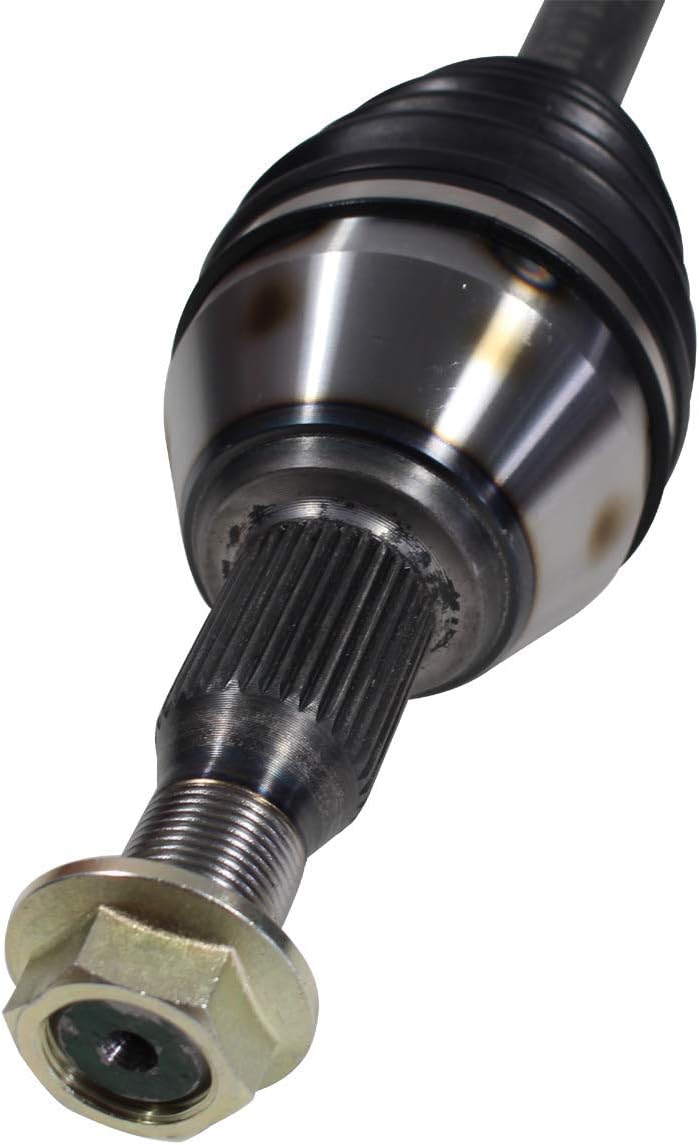
China manufacturer GJF Auto Drive Shaft Drive Axle for Mercedes-Benz R350 251 2006-2009 C-Me002-8h wholesaler
Product Description
Product Description
1.We are manufacturer of cv drive shaft,cv axle, cv joint and cv boot, we have more than 20-years experience in producing and selling auto parts.
2.We have strict quality control, the quality of our products is very good.
3.We are professional in different market around the world.
4.The reviews our customers given us are very positive, we have confidence in our products.
5.OEM/ODM is available, meet your requirements well.
6.Large warehouse, huge stocks!!! friendly for those customers who want small quantity.
7.Ship products out very fastly, we have stock.
| Product Name | Drive shaft | Material | 42CrMo alloy steel |
| Car fitment | Benz | Warranty | 12 months |
| Model | R350/L 251 | Place of origin | ZHangZhoug, China |
| Productive year | 2006-2009 | MOQ | 4 PCS |
| OE number | 2513301901 | Delivery time | 1-7 days |
| OEM/ODM | Yes | Brand | GJF |
| Packing size | 82*23.5*23.5 | Payment | L/C,T/T,western Union,Cash,PayPal |
| Sample service | Depends on the situation of stock | Weight | 8.3KG |
Detailed Photos
Customer Review
Packaging & Shipping
FAQ
Calculating the Deflection of a Worm Shaft
In this article, we’ll discuss how to calculate the deflection of a worm gear’s worm shaft. We’ll also discuss the characteristics of a worm gear, including its tooth forces. And we’ll cover the important characteristics of a worm gear. Read on to learn more! Here are some things to consider before purchasing a worm gear. We hope you enjoy learning! After reading this article, you’ll be well-equipped to choose a worm gear to match your needs.
Calculation of worm shaft deflection
The main goal of the calculations is to determine the deflection of a worm. Worms are used to turn gears and mechanical devices. This type of transmission uses a worm. The worm diameter and the number of teeth are inputted into the calculation gradually. Then, a table with proper solutions is shown on the screen. After completing the table, you can then move on to the main calculation. You can change the strength parameters as well.
The maximum worm shaft deflection is calculated using the finite element method (FEM). The model has many parameters, including the size of the elements and boundary conditions. The results from these simulations are compared to the corresponding analytical values to calculate the maximum deflection. The result is a table that displays the maximum worm shaft deflection. The tables can be downloaded below. You can also find more information about the different deflection formulas and their applications.
The calculation method used by DIN EN 10084 is based on the hardened cemented worm of 16MnCr5. Then, you can use DIN EN 10084 (CuSn12Ni2-C-GZ) and DIN EN 1982 (CuAl10Fe5Ne5-C-GZ). Then, you can enter the worm face width, either manually or using the auto-suggest option.
Common methods for the calculation of worm shaft deflection provide a good approximation of deflection but do not account for geometric modifications on the worm. While Norgauer’s 2021 approach addresses these issues, it fails to account for the helical winding of the worm teeth and overestimates the stiffening effect of gearing. More sophisticated approaches are required for the efficient design of thin worm shafts.
Worm gears have a low noise and vibration compared to other types of mechanical devices. However, worm gears are often limited by the amount of wear that occurs on the softer worm wheel. Worm shaft deflection is a significant influencing factor for noise and wear. The calculation method for worm gear deflection is available in ISO/TR 14521, DIN 3996, and AGMA 6022.
The worm gear can be designed with a precise transmission ratio. The calculation involves dividing the transmission ratio between more stages in a gearbox. Power transmission input parameters affect the gearing properties, as well as the material of the worm/gear. To achieve a better efficiency, the worm/gear material should match the conditions that are to be experienced. The worm gear can be a self-locking transmission.
The worm gearbox contains several machine elements. The main contributors to the total power loss are the axial loads and bearing losses on the worm shaft. Hence, different bearing configurations are studied. One type includes locating/non-locating bearing arrangements. The other is tapered roller bearings. The worm gear drives are considered when locating versus non-locating bearings. The analysis of worm gear drives is also an investigation of the X-arrangement and four-point contact bearings.
Influence of tooth forces on bending stiffness of a worm gear
The bending stiffness of a worm gear is dependent on tooth forces. Tooth forces increase as the power density increases, but this also leads to increased worm shaft deflection. The resulting deflection can affect efficiency, wear load capacity, and NVH behavior. Continuous improvements in bronze materials, lubricants, and manufacturing quality have enabled worm gear manufacturers to produce increasingly high power densities.
Standardized calculation methods take into account the supporting effect of the toothing on the worm shaft. However, overhung worm gears are not included in the calculation. In addition, the toothing area is not taken into account unless the shaft is designed next to the worm gear. Similarly, the root diameter is treated as the equivalent bending diameter, but this ignores the supporting effect of the worm toothing.
A generalized formula is provided to estimate the STE contribution to vibratory excitation. The results are applicable to any gear with a meshing pattern. It is recommended that engineers test different meshing methods to obtain more accurate results. One way to test tooth-meshing surfaces is to use a finite element stress and mesh subprogram. This software will measure tooth-bending stresses under dynamic loads.
The effect of tooth-brushing and lubricant on bending stiffness can be achieved by increasing the pressure angle of the worm pair. This can reduce tooth bending stresses in the worm gear. A further method is to add a load-loaded tooth-contact analysis (CCTA). This is also used to analyze mismatched ZC1 worm drive. The results obtained with the technique have been widely applied to various types of gearing.
In this study, we found that the ring gear’s bending stiffness is highly influenced by the teeth. The chamfered root of the ring gear is larger than the slot width. Thus, the ring gear’s bending stiffness varies with its tooth width, which increases with the ring wall thickness. Furthermore, a variation in the ring wall thickness of the worm gear causes a greater deviation from the design specification.
To understand the impact of the teeth on the bending stiffness of a worm gear, it is important to know the root shape. Involute teeth are susceptible to bending stress and can break under extreme conditions. A tooth-breakage analysis can control this by determining the root shape and the bending stiffness. The optimization of the root shape directly on the final gear minimizes the bending stress in the involute teeth.
The influence of tooth forces on the bending stiffness of a worm gear was investigated using the CZPT Spiral Bevel Gear Test Facility. In this study, multiple teeth of a spiral bevel pinion were instrumented with strain gages and tested at speeds ranging from static to 14400 RPM. The tests were performed with power levels as high as 540 kW. The results obtained were compared with the analysis of a three-dimensional finite element model.
Characteristics of worm gears
Worm gears are unique types of gears. They feature a variety of characteristics and applications. This article will examine the characteristics and benefits of worm gears. Then, we’ll examine the common applications of worm gears. Let’s take a look! Before we dive in to worm gears, let’s review their capabilities. Hopefully, you’ll see how versatile these gears are.
A worm gear can achieve massive reduction ratios with little effort. By adding circumference to the wheel, the worm can greatly increase its torque and decrease its speed. Conventional gearsets require multiple reductions to achieve the same reduction ratio. Worm gears have fewer moving parts, so there are fewer places for failure. However, they can’t reverse the direction of power. This is because the friction between the worm and wheel makes it impossible to move the worm backwards.
Worm gears are widely used in elevators, hoists, and lifts. They are particularly useful in applications where stopping speed is critical. They can be incorporated with smaller brakes to ensure safety, but shouldn’t be relied upon as a primary braking system. Generally, they are self-locking, so they are a good choice for many applications. They also have many benefits, including increased efficiency and safety.
Worm gears are designed to achieve a specific reduction ratio. They are typically arranged between the input and output shafts of a motor and a load. The 2 shafts are often positioned at an angle that ensures proper alignment. Worm gear gears have a center spacing of a frame size. The center spacing of the gear and worm shaft determines the axial pitch. For instance, if the gearsets are set at a radial distance, a smaller outer diameter is necessary.
Worm gears’ sliding contact reduces efficiency. But it also ensures quiet operation. The sliding action limits the efficiency of worm gears to 30% to 50%. A few techniques are introduced herein to minimize friction and to produce good entrance and exit gaps. You’ll soon see why they’re such a versatile choice for your needs! So, if you’re considering purchasing a worm gear, make sure you read this article to learn more about its characteristics!
An embodiment of a worm gear is described in FIGS. 19 and 20. An alternate embodiment of the system uses a single motor and a single worm 153. The worm 153 turns a gear which drives an arm 152. The arm 152, in turn, moves the lens/mirr assembly 10 by varying the elevation angle. The motor control unit 114 then tracks the elevation angle of the lens/mirr assembly 10 in relation to the reference position.
The worm wheel and worm are both made of metal. However, the brass worm and wheel are made of brass, which is a yellow metal. Their lubricant selections are more flexible, but they’re limited by additive restrictions due to their yellow metal. Plastic on metal worm gears are generally found in light load applications. The lubricant used depends on the type of plastic, as many types of plastics react to hydrocarbons found in regular lubricant. For this reason, you need a non-reactive lubricant.
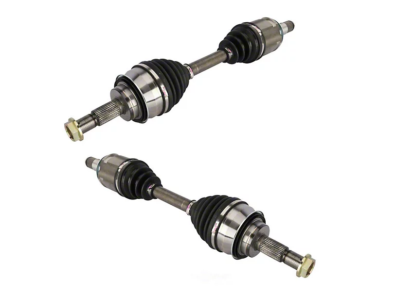
China high quality Gjf Left Side Drive Shaft Front Axle for Jeep Grand Cherokee 3.7 2006-2010 C-CH032-8h wholesaler
Product Description
Product Description
1.We are manufacturer of cv drive shaft,cv axle, cv joint and cv boot, we have more than 20-years experience in producing and selling auto parts.
2.We have strict quality control, the quality of our products is very good.
3.We are professional in different market around the world.
4.The reviews our customers given us are very positive, we have confidence in our products.
5.OEM/ODM is available, meet your requirements well.
6.Large warehouse, huge stocks!!! friendly for those customers who want some quantity.
7.Ship products out very fastly, we have stock.
| Product Name | Drive shaft | Material | 42CrMo alloy steel |
| Car fitment | Toyota | Warranty | 12 months |
| Model | Grand Cherokee 3.7/L 2006-2571 | Place of origin | ZHangZhoug, China |
| Certification | SGS/TUV/ISO | MOQ | 4 PCS |
| Transportation | Express/ by sea/ by air/ by land | Delivery time | 1-7 days |
| OEM/ODM | Yes | Brand | GJF |
| Advantages | large stocks/ deliver fastly/ strict quality supervision | Payment | L/C,T/T,western Union,Cash,PayPal |
| Sample service | Depends on the situation of stock | Weight | About 9KG |
Detailed Photos
Customer Review
Packaging & Shipping
FAQ
Calculating the Deflection of a Worm Shaft
In this article, we’ll discuss how to calculate the deflection of a worm gear’s worm shaft. We’ll also discuss the characteristics of a worm gear, including its tooth forces. And we’ll cover the important characteristics of a worm gear. Read on to learn more! Here are some things to consider before purchasing a worm gear. We hope you enjoy learning! After reading this article, you’ll be well-equipped to choose a worm gear to match your needs.
Calculation of worm shaft deflection
The main goal of the calculations is to determine the deflection of a worm. Worms are used to turn gears and mechanical devices. This type of transmission uses a worm. The worm diameter and the number of teeth are inputted into the calculation gradually. Then, a table with proper solutions is shown on the screen. After completing the table, you can then move on to the main calculation. You can change the strength parameters as well.
The maximum worm shaft deflection is calculated using the finite element method (FEM). The model has many parameters, including the size of the elements and boundary conditions. The results from these simulations are compared to the corresponding analytical values to calculate the maximum deflection. The result is a table that displays the maximum worm shaft deflection. The tables can be downloaded below. You can also find more information about the different deflection formulas and their applications.
The calculation method used by DIN EN 10084 is based on the hardened cemented worm of 16MnCr5. Then, you can use DIN EN 10084 (CuSn12Ni2-C-GZ) and DIN EN 1982 (CuAl10Fe5Ne5-C-GZ). Then, you can enter the worm face width, either manually or using the auto-suggest option.
Common methods for the calculation of worm shaft deflection provide a good approximation of deflection but do not account for geometric modifications on the worm. While Norgauer’s 2021 approach addresses these issues, it fails to account for the helical winding of the worm teeth and overestimates the stiffening effect of gearing. More sophisticated approaches are required for the efficient design of thin worm shafts.
Worm gears have a low noise and vibration compared to other types of mechanical devices. However, worm gears are often limited by the amount of wear that occurs on the softer worm wheel. Worm shaft deflection is a significant influencing factor for noise and wear. The calculation method for worm gear deflection is available in ISO/TR 14521, DIN 3996, and AGMA 6022.
The worm gear can be designed with a precise transmission ratio. The calculation involves dividing the transmission ratio between more stages in a gearbox. Power transmission input parameters affect the gearing properties, as well as the material of the worm/gear. To achieve a better efficiency, the worm/gear material should match the conditions that are to be experienced. The worm gear can be a self-locking transmission.
The worm gearbox contains several machine elements. The main contributors to the total power loss are the axial loads and bearing losses on the worm shaft. Hence, different bearing configurations are studied. One type includes locating/non-locating bearing arrangements. The other is tapered roller bearings. The worm gear drives are considered when locating versus non-locating bearings. The analysis of worm gear drives is also an investigation of the X-arrangement and four-point contact bearings.
Influence of tooth forces on bending stiffness of a worm gear
The bending stiffness of a worm gear is dependent on tooth forces. Tooth forces increase as the power density increases, but this also leads to increased worm shaft deflection. The resulting deflection can affect efficiency, wear load capacity, and NVH behavior. Continuous improvements in bronze materials, lubricants, and manufacturing quality have enabled worm gear manufacturers to produce increasingly high power densities.
Standardized calculation methods take into account the supporting effect of the toothing on the worm shaft. However, overhung worm gears are not included in the calculation. In addition, the toothing area is not taken into account unless the shaft is designed next to the worm gear. Similarly, the root diameter is treated as the equivalent bending diameter, but this ignores the supporting effect of the worm toothing.
A generalized formula is provided to estimate the STE contribution to vibratory excitation. The results are applicable to any gear with a meshing pattern. It is recommended that engineers test different meshing methods to obtain more accurate results. One way to test tooth-meshing surfaces is to use a finite element stress and mesh subprogram. This software will measure tooth-bending stresses under dynamic loads.
The effect of tooth-brushing and lubricant on bending stiffness can be achieved by increasing the pressure angle of the worm pair. This can reduce tooth bending stresses in the worm gear. A further method is to add a load-loaded tooth-contact analysis (CCTA). This is also used to analyze mismatched ZC1 worm drive. The results obtained with the technique have been widely applied to various types of gearing.
In this study, we found that the ring gear’s bending stiffness is highly influenced by the teeth. The chamfered root of the ring gear is larger than the slot width. Thus, the ring gear’s bending stiffness varies with its tooth width, which increases with the ring wall thickness. Furthermore, a variation in the ring wall thickness of the worm gear causes a greater deviation from the design specification.
To understand the impact of the teeth on the bending stiffness of a worm gear, it is important to know the root shape. Involute teeth are susceptible to bending stress and can break under extreme conditions. A tooth-breakage analysis can control this by determining the root shape and the bending stiffness. The optimization of the root shape directly on the final gear minimizes the bending stress in the involute teeth.
The influence of tooth forces on the bending stiffness of a worm gear was investigated using the CZPT Spiral Bevel Gear Test Facility. In this study, multiple teeth of a spiral bevel pinion were instrumented with strain gages and tested at speeds ranging from static to 14400 RPM. The tests were performed with power levels as high as 540 kW. The results obtained were compared with the analysis of a three-dimensional finite element model.
Characteristics of worm gears
Worm gears are unique types of gears. They feature a variety of characteristics and applications. This article will examine the characteristics and benefits of worm gears. Then, we’ll examine the common applications of worm gears. Let’s take a look! Before we dive in to worm gears, let’s review their capabilities. Hopefully, you’ll see how versatile these gears are.
A worm gear can achieve massive reduction ratios with little effort. By adding circumference to the wheel, the worm can greatly increase its torque and decrease its speed. Conventional gearsets require multiple reductions to achieve the same reduction ratio. Worm gears have fewer moving parts, so there are fewer places for failure. However, they can’t reverse the direction of power. This is because the friction between the worm and wheel makes it impossible to move the worm backwards.
Worm gears are widely used in elevators, hoists, and lifts. They are particularly useful in applications where stopping speed is critical. They can be incorporated with smaller brakes to ensure safety, but shouldn’t be relied upon as a primary braking system. Generally, they are self-locking, so they are a good choice for many applications. They also have many benefits, including increased efficiency and safety.
Worm gears are designed to achieve a specific reduction ratio. They are typically arranged between the input and output shafts of a motor and a load. The 2 shafts are often positioned at an angle that ensures proper alignment. Worm gear gears have a center spacing of a frame size. The center spacing of the gear and worm shaft determines the axial pitch. For instance, if the gearsets are set at a radial distance, a smaller outer diameter is necessary.
Worm gears’ sliding contact reduces efficiency. But it also ensures quiet operation. The sliding action limits the efficiency of worm gears to 30% to 50%. A few techniques are introduced herein to minimize friction and to produce good entrance and exit gaps. You’ll soon see why they’re such a versatile choice for your needs! So, if you’re considering purchasing a worm gear, make sure you read this article to learn more about its characteristics!
An embodiment of a worm gear is described in FIGS. 19 and 20. An alternate embodiment of the system uses a single motor and a single worm 153. The worm 153 turns a gear which drives an arm 152. The arm 152, in turn, moves the lens/mirr assembly 10 by varying the elevation angle. The motor control unit 114 then tracks the elevation angle of the lens/mirr assembly 10 in relation to the reference position.
The worm wheel and worm are both made of metal. However, the brass worm and wheel are made of brass, which is a yellow metal. Their lubricant selections are more flexible, but they’re limited by additive restrictions due to their yellow metal. Plastic on metal worm gears are generally found in light load applications. The lubricant used depends on the type of plastic, as many types of plastics react to hydrocarbons found in regular lubricant. For this reason, you need a non-reactive lubricant.
China manufacturer GJF Transmiss Shaft Joint Axle for Mazda M3 Drive Shaft 2.0 at 06-19 C-Mz086-8h wholesaler
Product Description
Product Description
1.We are manufacturer of cv drive shaft,cv axle, cv joint and cv boot, we have more than 20-years experience in producing and selling auto parts.
2.We have strict quality control, the quality of our products is very good.
3.We are professional in different market around the world.
4.The reviews our customers given us are very positive, we have confidence in our products.
5.OEM/ODM is available, meet your requirements well.
6.Large warehouse, huge stocks!!! friendly for those customers who want small quantity.
7.Ship products out very fastly, we have stock.
| Product Name | Drive shaft | Material | 42CrMo alloy steel |
| Car fitment | Mitsubishi | Warranty | 12 months |
| Model | M3 2.0 AT/R 2008-2011 | Place of origin | ZHangZhoug, China |
| Brand | GJF | MOQ | 4 PCS |
| OE number | GG44-25-500F | Delivery time | 1-7 days |
| OEM/ODM | Yes | Brand | GJF |
| Packing size | 72*23.5*23.5 | Payment | L/C,T/T,western Union,Cash,PayPal |
| Sample service | Depends on the situation of stock | Weight | 6.6KG |
Detailed Photos
Customer Review
Packaging & Shipping
FAQ
Types of Splines
There are 4 types of splines: Involute, Parallel key, helical, and ball. Learn about their characteristics. And, if you’re not sure what they are, you can always request a quotation. These splines are commonly used for building special machinery, repair jobs, and other applications. The CZPT Manufacturing Company manufactures these shafts. It is a specialty manufacturer and we welcome your business.
Involute splines
The involute spline provides a more rigid and durable structure, and is available in a variety of diameters and spline counts. Generally, steel, carbon steel, or titanium are used as raw materials. Other materials, such as carbon fiber, may be suitable. However, titanium can be difficult to produce, so some manufacturers make splines using other constituents.
When splines are used in shafts, they prevent parts from separating during operation. These features make them an ideal choice for securing mechanical assemblies. Splines with inward-curving grooves do not have sharp corners and are therefore less likely to break or separate while they are in operation. These properties help them to withstand high-speed operations, such as braking, accelerating, and reversing.
A male spline is fitted with an externally-oriented face, and a female spline is inserted through the center. The teeth of the male spline typically have chamfered tips to provide clearance with the transition area. The radii and width of the teeth of a male spline are typically larger than those of a female spline. These specifications are specified in ANSI or DIN design manuals.
The effective tooth thickness of a spline depends on the involute profile error and the lead error. Also, the spacing of the spline teeth and keyways can affect the effective tooth thickness. Involute splines in a splined shaft are designed so that at least 25 percent of the spline teeth engage during coupling, which results in a uniform distribution of load and wear on the spline.
Parallel key splines
A parallel splined shaft has a helix of equal-sized grooves around its circumference. These grooves are generally parallel or involute. Splines minimize stress concentrations in stationary joints and allow linear and rotary motion. Splines may be cut or cold-rolled. Cold-rolled splines have more strength than cut spines and are often used in applications that require high strength, accuracy, and a smooth surface.
A parallel key splined shaft features grooves and keys that are parallel to the axis of the shaft. This design is best suited for applications where load bearing is a primary concern and a smooth motion is needed. A parallel key splined shaft can be made from alloy steels, which are iron-based alloys that may also contain chromium, nickel, molybdenum, copper, or other alloying materials.
A splined shaft can be used to transmit torque and provide anti-rotation when operating as a linear guide. These shafts have square profiles that match up with grooves in a mating piece and transmit torque and rotation. They can also be easily changed in length, and are commonly used in aerospace. Its reliability and fatigue life make it an excellent choice for many applications.
The main difference between a parallel key splined shaft and a keyed shaft is that the former offers more flexibility. They lack slots, which reduce torque-transmitting capacity. Splines offer equal load distribution along the gear teeth, which translates into a longer fatigue life for the shaft. In agricultural applications, shaft life is essential. Agricultural equipment, for example, requires the ability to function at high speeds for extended periods of time.
Involute helical splines
Involute splines are a common design for splined shafts. They are the most commonly used type of splined shaft and feature equal spacing among their teeth. The teeth of this design are also shorter than those of the parallel spline shaft, reducing stress concentration. These splines can be used to transmit power to floating or permanently fixed gears, and reduce stress concentrations in the stationary joint. Involute splines are the most common type of splined shaft, and are widely used for a variety of applications in automotive, machine tools, and more.
Involute helical spline shafts are ideal for applications involving axial motion and rotation. They allow for face coupling engagement and disengagement. This design also allows for a larger diameter than a parallel spline shaft. The result is a highly efficient gearbox. Besides being durable, splines can also be used for other applications involving torque and energy transfer.
A new statistical model can be used to determine the number of teeth that engage for a given load. These splines are characterized by a tight fit at the major diameters, thereby transferring concentricity from the shaft to the female spline. A male spline has chamfered tips for clearance with the transition area. ANSI and DIN design manuals specify the different classes of fit.
The design of involute helical splines is similar to that of gears, and their ridges or teeth are matched with the corresponding grooves in a mating piece. It enables torque and rotation to be transferred to a mate piece while maintaining alignment of the 2 components. Different types of splines are used in different applications. Different splines can have different levels of tooth height.
Involute ball splines
When splines are used, they allow the shaft and hub to engage evenly over the shaft’s entire circumference. Because the teeth are evenly spaced, the load that they can transfer is uniform and their position is always the same regardless of shaft length. Whether the shaft is used to transmit torque or to transmit power, splines are a great choice. They provide maximum strength and allow for linear or rotary motion.
There are 3 basic types of splines: helical, crown, and ball. Crown splines feature equally spaced grooves. Crown splines feature involute sides and parallel sides. Helical splines use involute teeth and are often used in small diameter shafts. Ball splines contain a ball bearing inside the splined shaft to facilitate rotary motion and minimize stress concentration in stationary joints.
The 2 types of splines are classified under the ANSI classes of fit. Fillet root splines have teeth that mesh along the longitudinal axis of rotation. Flat root splines have similar teeth, but are intended to optimize strength for short-term use. Both types of splines are important for ensuring the shaft aligns properly and is not misaligned.
The friction coefficient of the hub is a complex process. When the hub is off-center, the center moves in predictable but irregular motion. Moreover, when the shaft is centered, the center may oscillate between being centered and being off-center. To compensate for this, the torque must be adequate to keep the shaft in its axis during all rotation angles. While straight-sided splines provide similar centering, they have lower misalignment load factors.
Keyed shafts
Essentially, splined shafts have teeth or ridges that fit together to transfer torque. Because splines are not as tall as involute gears, they offer uniform torque transfer. Additionally, they provide the opportunity for torque and rotational changes and improve wear resistance. In addition to their durability, splined shafts are popular in the aerospace industry and provide increased reliability and fatigue life.
Keyed shafts are available in different materials, lengths, and diameters. When used in high-power drive applications, they offer higher torque and rotational speeds. The higher torque they produce helps them deliver power to the gearbox. However, they are not as durable as splined shafts, which is why the latter is usually preferred in these applications. And while they’re more expensive, they’re equally effective when it comes to torque delivery.
Parallel keyed shafts have separate profiles and ridges and are used in applications requiring accuracy and precision. Keyed shafts with rolled splines are 35% stronger than cut splines and are used where precision is essential. These splines also have a smooth finish, which can make them a good choice for precision applications. They also work well with gears and other mechanical systems that require accurate torque transfer.
Carbon steel is another material used for splined shafts. Carbon steel is known for its malleability, and its shallow carbon content helps create reliable motion. However, if you’re looking for something more durable, consider ferrous steel. This type contains metals such as nickel, chromium, and molybdenum. And it’s important to remember that carbon steel is not the only material to consider.
China supplier CV Axle for Accent III (MC) 48t Hyundai Axle Shaft wholesaler
Product Description
Product Description
Our compay always insists high-quality standard producing and continually improve ourselves since the very beginning of company’s establishment, we always contribute to make perfect combination of equipment and technology, made the high stable quality.
| Part Name | CV AXLE |
| Brand | AUTOJET/AAE/STOP/ as customers requirements |
| Application | Auto Transmission System |
| car maker | All AMERICAN,BIRTITSH, JAPANESS, and KOREAN |
| Placement on Vehicle | Right/ Left |
| Material | Iron/Steel |
| Warranty | 12 Months |
| Sample | Available |
| Price | 31$-79$ |
| Place of origin | Any Chinese port |
| Delivery time | 30-45 days after confirmed |
| Packing | Processional |
| MOQ | 100 PCS |
| Payment | L/C,T/T,Western Union,PayPal |
Detailed Photos
Main Products
Company Profile
ZheJiang CZPT Macinery equipments is a new developing manufacturing company. Producing Auto parts production lines. As well we have 15 years of exporting auto parts for all automotive products. As after market supplies. Our main products are SHOCK ABSORBING, POWER STEERING SYSTEMS, SUSPENSION, CV AXLE, CV JONTS, and AUTO LIGHTS. We have our own brands and we do customize brand for customers requirements. Our products are produced under quality control team. Two advantage we offer; Genuine parts quality and After market price best value parts. Our products has 98% warranty for 1 year form date of use. Some items are warranty per KM 98% means we accept a claim if the damaged parts more then 2% of the quantity up to manufacturing fault for After Sales Service We have different solutions for different customers. Our company is sincerely willing to cooperate with enterprises from all over the world in order to realize a CZPT situation since the trend of economic globalization has developed with an irresistible force.
Packaging & Shipping
FAQ
1.Are you a factory or a trading company ?
We are a factory and trading company at the same time.
2.Where is your company located ? How can I visit there ?
Our company is located in HangZhou, all clients, from home and abroad, are warmly welcomed to visit us .
3.How about the quality of the products ?
Our products are of high quality and we have registered and reputable brands.
4.What’s the MOQ for each items ?
100 pieces.
5.Could we supply samples ?
We offer samples,but the samples should be paid.
6.What’s the delivery time ?
30-45 working days after confirmed
7.What’s our shipping ways ?
We can provide different types of shipping such as sea, air, and land.
Screw Sizes and Their Uses
Screws have different sizes and features. This article will discuss screw sizes and their uses. There are 2 main types: right-handed and left-handed screw shafts. Each screw features a point that drills into the object. Flat tipped screws, on the other hand, need a pre-drilled hole. These screw sizes are determined by the major and minor diameters. To determine which size of screw you need, measure the diameter of the hole and the screw bolt’s thread depth.
The major diameter of a screw shaft
The major diameter of a screw shaft is the distance from the outer edge of the thread on 1 side to the tip of the other. The minor diameter is the inner smooth part of the screw shaft. The major diameter of a screw is typically between 2 and 16 inches. A screw with a pointy tip has a smaller major diameter than 1 without. In addition, a screw with a larger major diameter will have a wider head and drive.
The thread of a screw is usually characterized by its pitch and angle of engagement. The pitch is the angle formed by the helix of a thread, while the crest forms the surface of the thread corresponding to the major diameter of the screw. The pitch angle is the angle between the gear axis and the pitch surface. Screws without self-locking threads have multiple starts, or helical threads.
The pitch is a crucial component of a screw’s threading system. Pitch is the distance from a given thread point to the corresponding point of the next thread on the same shaft. The pitch line is 1 element of pitch diameter. The pitch line, or lead, is a crucial dimension for the thread of a screw, as it controls the amount of thread that will advance during a single turn.
The pitch diameter of a screw shaft
When choosing the appropriate screw, it is important to know its pitch diameter and pitch line. The pitch line designates the distance between adjacent thread sides. The pitch diameter is also known as the mean area of the screw shaft. Both of these dimensions are important when choosing the correct screw. A screw with a pitch of 1/8 will have a mechanical advantage of 6.3. For more information, consult an application engineer at Roton.
The pitch diameter of a screw shaft is measured as the distance between the crest and the root of the thread. Threads that are too long or too short will not fit together in an assembly. To measure pitch, use a measuring tool with a metric scale. If the pitch is too small, it will cause the screw to loosen or get stuck. Increasing the pitch will prevent this problem. As a result, screw diameter is critical.
The pitch diameter of a screw shaft is measured from the crest of 1 thread to the corresponding point on the next thread. Measurement is made from 1 thread to another, which is then measured using the pitch. Alternatively, the pitch diameter can be approximated by averaging the major and minor diameters. In most cases, the pitch diameter of a screw shaft is equal to the difference between the two.
The thread depth of a screw shaft
Often referred to as the major diameter, the thread depth is the outermost diameter of the screw. To measure the thread depth of a screw, use a steel rule, micrometer, or caliper. In general, the first number in the thread designation indicates the major diameter of the thread. If a section of the screw is worn, the thread depth will be smaller, and vice versa. Therefore, it is good practice to measure the section of the screw that receives the least amount of use.
In screw manufacturing, the thread depth is measured from the crest of the screw to the root. The pitch diameter is halfway between the major and minor diameters. The lead diameter represents the amount of linear distance traveled in 1 revolution. As the lead increases, the load capacity decreases. This measurement is primarily used in the construction of screws. However, it should not be used for precision machines. The thread depth of a screw shaft is essential for achieving accurate screw installation.
To measure the thread depth of a screw shaft, the manufacturer must first determine how much material the thread is exposed to. If the thread is exposed to side loads, it can cause the nut to wedge. Because the nut will be side loaded, its thread flanks will contact the nut. The less clearance between the nut and the screw, the lower the clearance between the nut and the screw. However, if the thread is centralized, there is no risk of the nut wedgeing.
The lead of a screw shaft
Pitch and lead are 2 measurements of a screw’s linear distance per turn. They’re often used interchangeably, but their definitions are not the same. The difference between them lies in the axial distance between adjacent threads. For single-start screws, the pitch is equal to the lead, while the lead of a multi-start screw is greater than the pitch. This difference is often referred to as backlash.
There are 2 ways to calculate the pitch and lead of a screw. For single-start screws, the lead and pitch are equal. Multiple-start screws, on the other hand, have multiple starts. The pitch of a multiple-start screw is the same as its lead, but with 2 or more threads running the length of the screw shaft. A square-thread screw is a better choice in applications requiring high load-bearing capacity and minimal friction losses.
The PV curve defines the safe operating limits of lead screw assemblies. It describes the inverse relationship between contact surface pressure and sliding velocity. As the load increases, the lead screw assembly must slow down in order to prevent irreversible damage from frictional heat. Furthermore, a lead screw assembly with a polymer nut must reduce rpm as the load increases. The more speed, the lower the load capacity. But, the PV factor must be below the maximum allowed value of the material used to make the screw shaft.
The thread angle of a screw shaft
The angle between the axes of a thread and the helix of a thread is called the thread angle. A unified thread has a 60-degree angle in all directions. Screws can have either a tapped hole or a captive screw. The screw pitch is measured in millimeters (mm) and is usually equal to the screw major diameter. In most cases, the thread angle will be equal to 60-degrees.
Screws with different angles have various degrees of thread. Originally, this was a problem because of the inconsistency in the threading. However, Sellers’s thread was easier to manufacture and was soon adopted as a standard throughout the United States. The United States government began to adopt this thread standard in the mid-1800s, and several influential corporations in the railroad industry endorsed it. The resulting standard is called the United States Standard thread, and it became part of the ASA’s Vol. 1 publication.
There are 2 types of screw threads: coarse and fine. The latter is easier to tighten and achieves tension at lower torques. On the other hand, the coarse thread is deeper than the fine one, making it easier to apply torque to the screw. The thread angle of a screw shaft will vary from bolt to bolt, but they will both fit in the same screw. This makes it easier to select the correct screw.
The tapped hole (or nut) into which the screw fits
A screw can be re-threaded without having to replace it altogether. The process is different than that of a standard bolt, because it requires threading and tapping. The size of a screw is typically specified by its major and minor diameters, which is the inside distance between threads. The thread pitch, which is the distance between each thread, is also specified. Thread pitch is often expressed in threads per inch.
Screws and bolts have different thread pitches. A coarse thread has fewer threads per inch and a longer distance between threads. It is therefore larger in diameter and longer than the material it is screwed into. A coarse thread is often designated with an “A” or “B” letter. The latter is generally used in smaller-scale metalworking applications. The class of threading is called a “threaded hole” and is designated by a letter.
A tapped hole is often a complication. There is a wide range of variations between the sizes of threaded holes and nut threads, so the tapped hole is a critical dimension in many applications. However, even if you choose a threaded screw that meets the requisite tolerance, there may be a mismatch in the thread pitch. This can prevent the screw from freely rotating.
China wholesaler CV Axle for Corolla (_E8_) 1.3 (AE80) 1993-2000 Drive Shaft CZPT with Hot selling
Product Description
Product Description
Our compay always insists high-quality standard producing and continually improve ourselves since the very beginning of company’s establishment, we always contribute to make perfect combination of equipment and technology, made the high stable quality.
Detailed Photos
Main Products
Company Profile
ZheJiang CZPT Macinery equipments is a new developing manufacturing company with 7M$ capital. Producing Auto parts production lines. As well we have 15 years of exporting auto parts for Japanese and Korean automotive products. As after market supplies. Our main products are SHOCK ABSORBING, POWER STEERING SYSTEMS, SUSPENSION, CV AXLE, CV JONTS, and AUTO LIGHTS. We have our own brands and we do customize brand for customers requirements. Our products are produced under quality control team. Two advantage we offer; Genuine parts quality and After market price best value parts. Our products has 98% warranty for 1 year form date of use. Some items are warranty per KM 98% means we accept a claim if the damaged parts more then 2% of the quantity up to manufacturing fault for After Sales Service We have different solutions for different customers. Our company is sincerely willing to cooperate with enterprises from all over the world in order to realize a CZPT situation since the trend of economic globalization has developed with an irresistible force.
Packaging & Shipping
FAQ
1.Are you a factory or a trading company ?
We are a factory and trading company at the same time.
2.Where is your company located ? How can I visit there ?
Our company is located in HangZhou, all clients, from home and abroad, are warmly welcomed to visit us .
3.How about the quality of the products ?
Our products are of high quality and we have registered and reputable brands.
4.What’s the MOQ for each items ?
50 pieces.
5.Could we supply samples ?
We offer samples,but the samples should be paid.
6.What’s the delivery time ?
15-20 working days
7.What’s our shipping ways ?
We can provide different types of shipping such as sea, air, and land.
Types of Splines
There are 4 types of splines: Involute, Parallel key, helical, and ball. Learn about their characteristics. And, if you’re not sure what they are, you can always request a quotation. These splines are commonly used for building special machinery, repair jobs, and other applications. The CZPT Manufacturing Company manufactures these shafts. It is a specialty manufacturer and we welcome your business.
Involute splines
The involute spline provides a more rigid and durable structure, and is available in a variety of diameters and spline counts. Generally, steel, carbon steel, or titanium are used as raw materials. Other materials, such as carbon fiber, may be suitable. However, titanium can be difficult to produce, so some manufacturers make splines using other constituents.
When splines are used in shafts, they prevent parts from separating during operation. These features make them an ideal choice for securing mechanical assemblies. Splines with inward-curving grooves do not have sharp corners and are therefore less likely to break or separate while they are in operation. These properties help them to withstand high-speed operations, such as braking, accelerating, and reversing.
A male spline is fitted with an externally-oriented face, and a female spline is inserted through the center. The teeth of the male spline typically have chamfered tips to provide clearance with the transition area. The radii and width of the teeth of a male spline are typically larger than those of a female spline. These specifications are specified in ANSI or DIN design manuals.
The effective tooth thickness of a spline depends on the involute profile error and the lead error. Also, the spacing of the spline teeth and keyways can affect the effective tooth thickness. Involute splines in a splined shaft are designed so that at least 25 percent of the spline teeth engage during coupling, which results in a uniform distribution of load and wear on the spline.
Parallel key splines
A parallel splined shaft has a helix of equal-sized grooves around its circumference. These grooves are generally parallel or involute. Splines minimize stress concentrations in stationary joints and allow linear and rotary motion. Splines may be cut or cold-rolled. Cold-rolled splines have more strength than cut spines and are often used in applications that require high strength, accuracy, and a smooth surface.
A parallel key splined shaft features grooves and keys that are parallel to the axis of the shaft. This design is best suited for applications where load bearing is a primary concern and a smooth motion is needed. A parallel key splined shaft can be made from alloy steels, which are iron-based alloys that may also contain chromium, nickel, molybdenum, copper, or other alloying materials.
A splined shaft can be used to transmit torque and provide anti-rotation when operating as a linear guide. These shafts have square profiles that match up with grooves in a mating piece and transmit torque and rotation. They can also be easily changed in length, and are commonly used in aerospace. Its reliability and fatigue life make it an excellent choice for many applications.
The main difference between a parallel key splined shaft and a keyed shaft is that the former offers more flexibility. They lack slots, which reduce torque-transmitting capacity. Splines offer equal load distribution along the gear teeth, which translates into a longer fatigue life for the shaft. In agricultural applications, shaft life is essential. Agricultural equipment, for example, requires the ability to function at high speeds for extended periods of time.
Involute helical splines
Involute splines are a common design for splined shafts. They are the most commonly used type of splined shaft and feature equal spacing among their teeth. The teeth of this design are also shorter than those of the parallel spline shaft, reducing stress concentration. These splines can be used to transmit power to floating or permanently fixed gears, and reduce stress concentrations in the stationary joint. Involute splines are the most common type of splined shaft, and are widely used for a variety of applications in automotive, machine tools, and more.
Involute helical spline shafts are ideal for applications involving axial motion and rotation. They allow for face coupling engagement and disengagement. This design also allows for a larger diameter than a parallel spline shaft. The result is a highly efficient gearbox. Besides being durable, splines can also be used for other applications involving torque and energy transfer.
A new statistical model can be used to determine the number of teeth that engage for a given load. These splines are characterized by a tight fit at the major diameters, thereby transferring concentricity from the shaft to the female spline. A male spline has chamfered tips for clearance with the transition area. ANSI and DIN design manuals specify the different classes of fit.
The design of involute helical splines is similar to that of gears, and their ridges or teeth are matched with the corresponding grooves in a mating piece. It enables torque and rotation to be transferred to a mate piece while maintaining alignment of the 2 components. Different types of splines are used in different applications. Different splines can have different levels of tooth height.
Involute ball splines
When splines are used, they allow the shaft and hub to engage evenly over the shaft’s entire circumference. Because the teeth are evenly spaced, the load that they can transfer is uniform and their position is always the same regardless of shaft length. Whether the shaft is used to transmit torque or to transmit power, splines are a great choice. They provide maximum strength and allow for linear or rotary motion.
There are 3 basic types of splines: helical, crown, and ball. Crown splines feature equally spaced grooves. Crown splines feature involute sides and parallel sides. Helical splines use involute teeth and are often used in small diameter shafts. Ball splines contain a ball bearing inside the splined shaft to facilitate rotary motion and minimize stress concentration in stationary joints.
The 2 types of splines are classified under the ANSI classes of fit. Fillet root splines have teeth that mesh along the longitudinal axis of rotation. Flat root splines have similar teeth, but are intended to optimize strength for short-term use. Both types of splines are important for ensuring the shaft aligns properly and is not misaligned.
The friction coefficient of the hub is a complex process. When the hub is off-center, the center moves in predictable but irregular motion. Moreover, when the shaft is centered, the center may oscillate between being centered and being off-center. To compensate for this, the torque must be adequate to keep the shaft in its axis during all rotation angles. While straight-sided splines provide similar centering, they have lower misalignment load factors.
Keyed shafts
Essentially, splined shafts have teeth or ridges that fit together to transfer torque. Because splines are not as tall as involute gears, they offer uniform torque transfer. Additionally, they provide the opportunity for torque and rotational changes and improve wear resistance. In addition to their durability, splined shafts are popular in the aerospace industry and provide increased reliability and fatigue life.
Keyed shafts are available in different materials, lengths, and diameters. When used in high-power drive applications, they offer higher torque and rotational speeds. The higher torque they produce helps them deliver power to the gearbox. However, they are not as durable as splined shafts, which is why the latter is usually preferred in these applications. And while they’re more expensive, they’re equally effective when it comes to torque delivery.
Parallel keyed shafts have separate profiles and ridges and are used in applications requiring accuracy and precision. Keyed shafts with rolled splines are 35% stronger than cut splines and are used where precision is essential. These splines also have a smooth finish, which can make them a good choice for precision applications. They also work well with gears and other mechanical systems that require accurate torque transfer.
Carbon steel is another material used for splined shafts. Carbon steel is known for its malleability, and its shallow carbon content helps create reliable motion. However, if you’re looking for something more durable, consider ferrous steel. This type contains metals such as nickel, chromium, and molybdenum. And it’s important to remember that carbon steel is not the only material to consider.