Product Description
What is railway axle
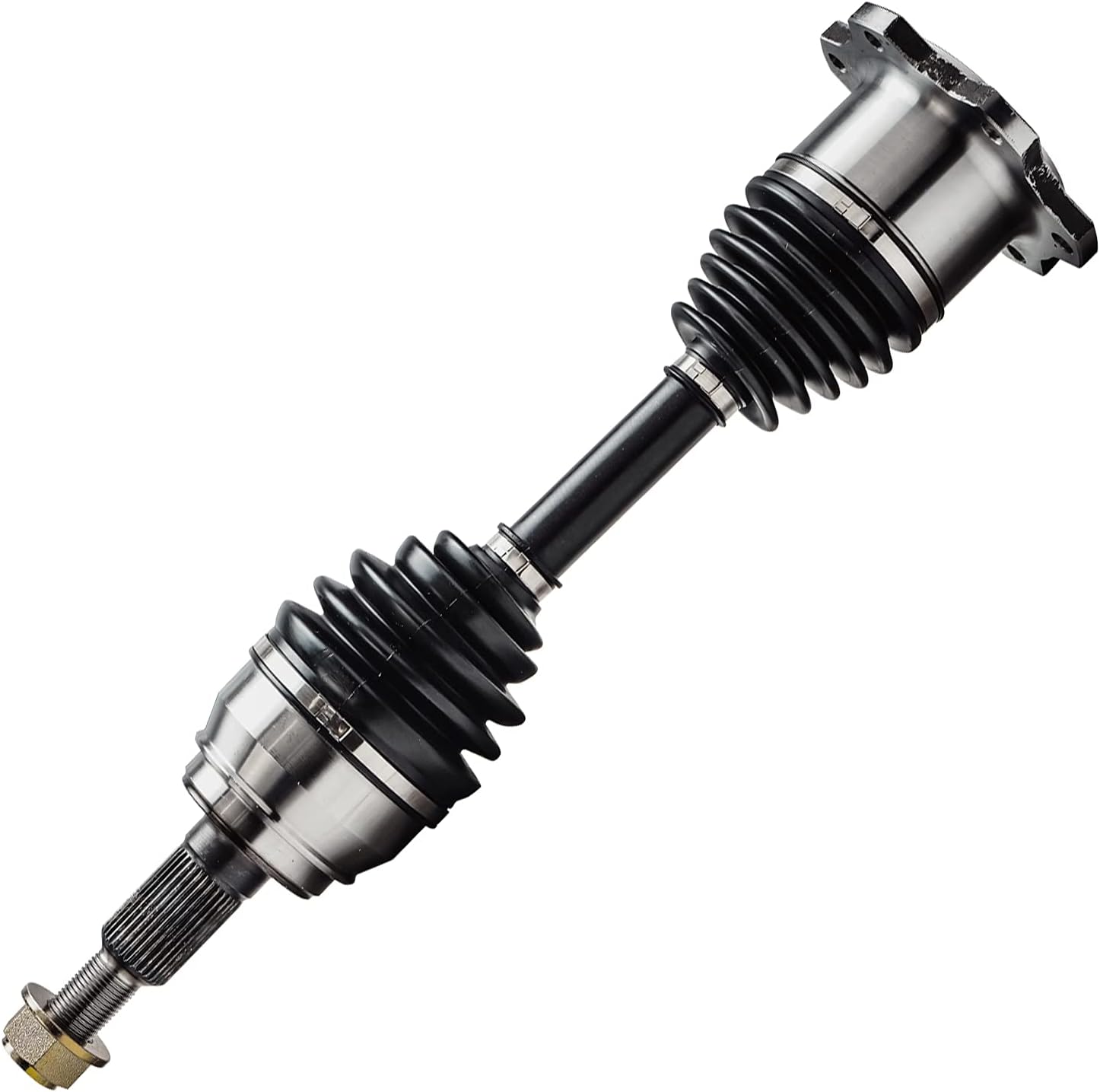
Railway axles are generally used in railway vehicles and are mechanical parts that connect 2 train wheels.
Our Railway axle applications:
1. Our railway axle can be used in railway locomotives, trucks, passenger cars, and high-speed trains.
2. Our railway axle can meet the needs of high speed, high power, large diameter, heavy load, and different gauges.
3. Our railway axles can also be applied to axles for various urban rail vehicles.
In addition, I can also produce many types of engineering, industrial shafts and other products.
| Product Name | Railway Axles |
| Wide Material | KINGRAIL PARTS axles wide range of raw material steel support LZ50, JZ45,AAT Grade F, EA1N, EA1T, EA4T, IRS 16/95, SFA60A, and et |
| Axle Type | Drive axle with multiple seats, Locomotive axles, Non-driven freight wagon axle, Passenger coach axle. |
| Axle Diameter | Φ90mm~Φ280mm |
| Alxe Length | 1600mm~2650mm |
| Test | Chemical analysis, Metallographic, Mechnical analysis, Ultrasonic testing, Magnetic testing, Impact testing, Hardness testing, Surface quality and dimension report |
| Certifications | ISO9001,ISO14001, OHSAS18001, AAR, IRIS, TSI |
Production process of the railway axle:
1. Billet Steel Review 2. Cutting 3. Heating 4. Forging 5. Straightening 6. Heat Treatment 7. Sampling Test 8. Ultrasonic Inspection 9. Rough Machining 10. Semi-Finish Machining 11. Finish Machining 12. Granding 13.Magnetic Particle Testing 14. Packing
| Quality Test for Raiwlay Axle | |||
| Chemical Analysis | Metallographic | Mechanical Analysis | Ultrasonic Testing |
| Magnetic Testing | Impact Testing | Hardness Testing | Surface Quality |
| Diemension Checks(CMM) | Customers’ acceptance check or third party check | ||
Packing&Shipping
Package : axles are fixed by wood frame and steel bars in wooden cases
Wooden cases : export wooden cases with fumigation certifications
Why choose CZPT Parets Railway Axle
1. We can provide various finished and semi-finished railway axles for railway rolling stock 2. Our factory has produced railway axles for more than 30 years and is an axle production company designated by the Chinese Ministry of Railways. 3. We have passed DB certification, AAR certification, and obtained Alstom’s B-level supplier qualification. We can mass produce axles that meet EN13261, AAR M101, UIC811 and Indian IRS R16 standards. 4. The axles we produce have been exported to Iran, Pakistan, Iraq, Egypt, Germany, India, Brazil, Chile, Myanmar, and other countries.
If you have any questions, pls feel free to contact us as below:
http:// /showroom/5fd55aec447165c4
MaHangZhou Ruika Metal Products Technology Co., Ltd. /* January 22, 2571 19:08:37 */!function(){function s(e,r){var a,o={};try{e&&e.split(“,”).forEach(function(e,t){e&&(a=e.match(/(.*?):(.*)$/))&&1
| After-sales Service: | Free After Service |
|---|---|
| Warranty: | Free After Service |
| Customized: | Customized |
| Certification: | ISO14001, ISO9001 |
| Type: | Railway Wagon Axles Locomotive Axle Train Axle |
| Production: | Forging, Rolled |
| Samples: |
US$ 1000/Piece
1 Piece(Min.Order) | |
|---|
| Customization: |
Available
| Customized Request |
|---|
Where can I find reputable sources for troubleshooting CV axle noises or vibrations?
When experiencing CV axle noises or vibrations, it’s important to consult reputable sources for accurate troubleshooting guidance. Here are some places where you can find reliable information to help troubleshoot CV axle issues:
1. Vehicle Manufacturer’s Official Website:
Start by visiting the official website of your vehicle’s manufacturer. They often provide comprehensive resources, including troubleshooting guides, technical articles, and maintenance manuals. Look for the section specific to your vehicle model and search for information related to CV axle noises or vibrations. The manufacturer’s website is a reliable source of information as it offers insights directly from the vehicle’s designers and engineers.
2. Online Forums and Communities:
Online automotive forums and communities can be valuable sources of information for troubleshooting CV axle issues. Websites such as Reddit, CarTalk, and various enthusiast forums dedicated to your specific vehicle make or model can provide insights from experienced car owners, mechanics, and enthusiasts who have encountered similar problems. Search for threads or posts related to CV axle noises or vibrations and read through discussions to gain valuable troubleshooting tips and solutions.
3. Repair Manuals or Service Guides:
Repair manuals or service guides specific to your vehicle can offer detailed information on troubleshooting and diagnosing CV axle issues. These manuals provide step-by-step instructions, diagrams, and specifications that can help you identify the root cause of the problem. You can find these manuals in printed form from automotive bookstores or online platforms that offer digital versions. Popular sources include Haynes Manuals, Chilton Manuals, and vehicle manufacturer’s official service manuals.
4. Automotive Websites and Blogs:
There are numerous reputable automotive websites and blogs that publish articles and guides on troubleshooting various car-related issues, including CV axle problems. Websites like AutoZone, RepairPal, and YourMechanic often provide detailed explanations, diagnostic procedures, and possible solutions for common CV axle noises or vibrations. These sources typically have a team of automotive experts or professional mechanics who contribute to their content, ensuring reliable information.
5. Professional Mechanics and Repair Shops:
If you are unable to diagnose or resolve the CV axle issues on your own, it’s best to consult with a professional mechanic or take your vehicle to a reputable repair shop. Mechanics have the expertise, experience, and specialized tools to accurately diagnose and troubleshoot CV axle problems. They can provide professional guidance and perform necessary repairs or replacements to resolve the issue effectively.
Remember to cross-reference information from multiple sources to ensure accuracy and reliability. Troubleshooting CV axle noises or vibrations can vary depending on the specific symptoms and vehicle make or model, so it’s important to consider various perspectives and expert opinions to make an informed diagnosis.
In summary, reputable sources for troubleshooting CV axle noises or vibrations include the vehicle manufacturer’s official website, online forums and communities, repair manuals or service guides, automotive websites and blogs, as well as professional mechanics and repair shops. Utilize these sources to gather reliable information and guidance for troubleshooting and resolving CV axle issues in your vehicle.
What are the signs of a worn CV joint, and how does it relate to the CV axle?
A CV joint is an essential component of a CV axle, and understanding the signs of a worn CV joint is crucial for identifying potential issues with the CV axle. Here’s an explanation of the signs of a worn CV joint and how it relates to the CV axle:
Signs of a Worn CV Joint:
1. Clicking or Popping Noises: One of the most common signs of a worn CV joint is a clicking or popping noise when turning. This noise is typically heard during low-speed maneuvers, such as when making a sharp turn or navigating a parking lot. The clicking or popping sound is caused by excessive play or looseness in the CV joint due to worn or damaged internal components.
2. Vibrations or Shuddering: A worn CV joint can cause vibrations or shuddering sensations, particularly during acceleration. This may be felt in the steering wheel, floorboard, or even the entire vehicle. The vibrations can occur due to an imbalance caused by a damaged CV joint, resulting in an uneven transfer of power to the wheels.
3. Grease Leakage: CV joints are packed with grease to lubricate the internal components and reduce friction. If a CV joint is worn or damaged, it may cause the grease to leak out. This can be observed as grease stains or splatters around the CV joint or on the inner side of the wheels. Grease leakage is a clear indication of a faulty CV joint that requires attention.
4. Torn CV Boot: The CV joint is protected by a rubber boot that seals in the grease and shields the joint from contaminants. A torn or damaged CV boot exposes the CV joint to dirt, debris, and moisture, leading to accelerated wear and potential damage. Inspecting the CV boots regularly and looking for any signs of tears or cracks is essential in identifying potential CV joint issues.
Relationship between CV Joint and CV Axle:
The CV joint is a critical component of the CV axle assembly. The CV axle, or constant velocity axle, is responsible for transmitting power from the transmission or differential to the wheels while allowing for flexible movement due to its jointed design. The CV joint is located at either end of the CV axle and connects it to the wheel hub assembly.
The CV joint enables the CV axle to transfer power smoothly to the wheels, even when the suspension moves up and down or when the wheels turn during steering. It allows for a constant velocity, hence the name “constant velocity joint.” The CV joint is designed with a ball-bearing or tripod-style mechanism that allows for articulation and rotation while maintaining a consistent speed and torque delivery to the wheels.
However, over time, the CV joint can wear out due to the constant movement, high loads, and exposure to contaminants. When a CV joint becomes worn or damaged, it can affect the overall performance and reliability of the CV axle. If left unaddressed, a worn CV joint can lead to further damage to the CV axle, potentially resulting in complete failure and loss of power transmission to the wheels.
Therefore, it’s crucial to pay attention to the signs of a worn CV joint and address them promptly by inspecting and replacing the affected CV axle or performing necessary repairs. Regular maintenance, including visual inspection of CV boots and listening for any abnormal noises during operation, can help detect CV joint issues early and prevent further damage to the CV axle assembly.
Can you explain the symptoms of a failing CV axle and how to diagnose the issue?
When a CV axle starts to fail, it can exhibit several symptoms that indicate potential issues. Recognizing these symptoms and properly diagnosing the problem is essential for timely repairs. Here’s an explanation of the symptoms of a failing CV axle and how to diagnose the issue:
Symptoms of a Failing CV Axle:
1. Clicking or popping sounds: One of the most common symptoms of a failing CV axle is a clicking or popping sound, especially when making turns. This sound may indicate that the CV joint is worn or damaged, causing it to bind or catch during rotation.
2. Vibration or shuddering: A failing CV axle can cause vibrations or shuddering felt in the vehicle’s steering wheel or floorboard. These vibrations are often most noticeable during acceleration, particularly when turning or maneuvering at low speeds.
3. Grease leakage: Inspect the CV axle boots for any signs of grease leakage. Damaged or torn CV boots can allow grease to escape, exposing the CV joints to dirt, debris, and moisture. This can lead to accelerated wear and eventual failure of the CV axle.
4. Excessive vibration during acceleration: If you experience strong vibrations during acceleration, it may indicate an issue with the CV axle. Damaged CV joints can cause the axle to become imbalanced, resulting in vibrations that intensify as the vehicle accelerates.
5. Difficulty in turning: A failing CV axle can make it difficult to turn the vehicle, especially at lower speeds. You may notice increased resistance or a jerking sensation when trying to steer.
6. Visible damage or excessive wear: Inspect the CV axle visually for any visible damage, such as cracks, tears, or excessive wear on the CV boots or joints. Physical damage or wear can impair the functionality of the CV axle and lead to failure.
Diagnosing a Failing CV Axle:
To diagnose a failing CV axle, you can perform the following steps:
1. Visual inspection: Inspect the CV axle visually for any signs of damage, leakage, or excessive wear. Look for cracks, tears, or loose components. Pay close attention to the CV boots and joints, as they are common areas of failure.
2. Listening for noises: While driving, listen for clicking, popping, or grinding sounds, especially during turns. These noises can indicate worn or damaged CV joints.
3. Test drive: Take the vehicle for a test drive and pay attention to any vibrations, shuddering, or difficulty in turning. Note when these symptoms occur, such as during acceleration, deceleration, or turns, as it can provide valuable information for diagnosis.
4. Inspection of CV boots: If you suspect a failing CV axle, inspect the CV boots for damage or leaks. Grease leakage or torn boots can be indicative of a failing CV joint.
5. Professional inspection: If you are uncertain about the diagnosis or lack the necessary tools and experience, it is recommended to have a qualified mechanic or technician inspect the CV axle. They can perform more in-depth diagnostics, such as checking for excessive play or movement in the CV joints, using specialized tools.
Remember, early detection and repair of a failing CV axle are crucial to prevent further damage to the drivetrain and ensure safe operation of the vehicle. If you suspect a failing CV axle based on the symptoms described, it is recommended to seek professional assistance for an accurate diagnosis and appropriate repairs.


editor by CX 2024-04-19
China OEM GJF CV Axle for CZPT Outlander Drive Shaft Axle Shaft 4WD Asx C-Mi072-8h with high quality
Product Description
Product Description
1.We are manufacturer of cv drive shaft,cv axle, cv joint and cv boot, we have more than 20-years experience in producing and selling auto parts.
2.We have strict quality control, the quality of our products is very good.
3.We are professional in different market around the world.
4.The reviews our customers given us are very positive, we have confidence in our products.
5.OEM/ODM is available, meet your requirements well.
6.Large warehouse, huge stocks!!! friendly for those customers who want small quantity.
7.Ship products out very fastly, we have stock.
| Product Name | Drive shaft | Material | 42CrMo alloy steel |
| Car fitment | Mitsubishi | Warranty | 12 months |
| Model | Outlander/ASX CW5 2.4/R 4WD 2008- | Place of origin | ZHangZhoug, China |
| Brand | GJF | MOQ | 4 PCS |
| OE number | 3815A066 | Delivery time | 1-7 days |
| OEM/ODM | Yes | Brand | GJF |
| Packing size | 102*23.5*23.5 | Payment | L/C,T/T,western Union,Cash,PayPal |
| Sample service | Depends on the situation of stock | Weight | 9.0KG |
Detailed Photos
Customer Review
Packaging & Shipping
FAQ
| After-sales Service: | 12 Months |
|---|---|
| Condition: | New |
| Axle Number: | 1 |
| Application: | Car |
| Certification: | ASTM, CE, DIN, ISO |
| Material: | Alloy |
| Samples: |
US$ 35/Piece
1 Piece(Min.Order) | |
|---|
| Customization: |
Available
| Customized Request |
|---|
What are the environmental considerations of recycling CV axles and related components?
When it comes to recycling CV axles and related components, there are several environmental considerations to take into account. Here’s a detailed explanation of the environmental aspects associated with recycling CV axles:
1. Metal Recycling:
CV axles and related components are typically made of various metals, such as steel and aluminum. Recycling these metals offers significant environmental benefits. Metal recycling reduces the need for extracting and processing raw materials, which helps conserve natural resources and reduces energy consumption. Additionally, recycling metals helps minimize the environmental impact associated with mining and refining processes, including habitat destruction, water pollution, and greenhouse gas emissions.
2. Hazardous Materials:
CV axles may contain hazardous materials or substances that require proper handling and disposal. For example, some axle components may have coatings or finishes that contain heavy metals or other toxic substances. When recycling CV axles, it’s important to follow proper procedures to remove and dispose of any hazardous materials safely. Recycling facilities and scrap metal yards have established protocols to handle hazardous materials to minimize their impact on the environment and human health.
3. Waste Reduction:
Recycling CV axles and related components contributes to waste reduction. Instead of ending up in landfills, these items can be processed and reused, reducing the amount of waste generated. By diverting CV axles from the waste stream, recycling helps conserve landfill space and reduces the potential for environmental contamination. It also reduces the need for new manufacturing, which further conserves resources and reduces associated environmental impacts.
4. Energy Savings:
Recycling CV axles and their components saves energy compared to producing new materials from virgin resources. The recycling process typically requires less energy compared to the extraction, refining, and manufacturing processes involved in producing new metal components. By recycling CV axles, energy consumption and associated greenhouse gas emissions can be reduced, contributing to a lower carbon footprint and mitigating climate change.
5. Proper Disposal:
In cases where CV axles or their components cannot be recycled due to damage or contamination, proper disposal becomes essential. It’s important to adhere to local regulations and guidelines for disposing of these items. Improper disposal can lead to environmental contamination, including soil and water pollution. Working with certified recycling facilities or scrap metal yards ensures that disposal is carried out in an environmentally responsible manner.
6. Extended Product Life Cycle:
Recycling CV axles and related components extends the product life cycle, reducing the need for new production. By reusing materials and components, the environmental impact associated with manufacturing new parts is minimized. Extending the life cycle of CV axles through recycling promotes resource conservation and reduces the overall environmental footprint of the automotive industry.
In summary, recycling CV axles and related components offers several environmental benefits. It conserves natural resources, reduces energy consumption, minimizes hazardous material disposal, promotes waste reduction, and contributes to a lower carbon footprint. Proper recycling and disposal practices play a crucial role in ensuring that these components are handled in an environmentally responsible manner, mitigating their impact on the environment and human health.
How often should CV axles be inspected and replaced as part of routine maintenance?
As part of routine maintenance, it’s important to regularly inspect CV axles to identify any signs of damage, wear, or potential issues. The frequency of inspection and replacement can vary depending on several factors, including the vehicle make and model, driving conditions, and manufacturer recommendations. Here’s a general guideline on how often CV axles should be inspected and replaced:
Inspection:
CV axles should be inspected at regular intervals to detect any early warning signs of damage or wear. A visual inspection can be performed during routine maintenance checks, such as oil changes or tire rotations. It’s recommended to inspect the CV axles at least once a year or every 12,000 to 15,000 miles (19,000 to 24,000 kilometers) as a general guideline.
However, certain driving conditions may require more frequent inspections. For example, if you frequently drive on rough or unpaved roads, or if you engage in off-road activities, more frequent inspections may be necessary due to the increased risk of damage or accelerated wear.
During the inspection, it’s important to check for the following signs of potential CV axle issues:
- Cracked or torn CV boots
- Leaking grease or lubricant
- Clicking, popping, or clunking noises when turning
- Vibrations or shuddering during acceleration
- Excessive play or looseness in the CV joints
If any of these signs are observed, further inspection by a qualified mechanic is recommended to assess the condition of the CV axles and determine if replacement is necessary.
Replacement:
The replacement interval for CV axles can vary depending on factors such as the vehicle’s age, mileage, driving conditions, and the specific recommendations of the vehicle manufacturer. In general, CV axles may need to be replaced between 80,000 to 150,000 miles (129,000 to 241,000 kilometers) or after 5 to 10 years of use.
However, it’s important to note that CV axles can fail prematurely due to various factors such as driving habits, environmental conditions, and maintenance history. If any signs of CV axle damage or failure are detected during the inspection or if there is a sudden and significant change in vehicle performance or handling, immediate replacement may be necessary regardless of the mileage or age of the axles.
It’s recommended to follow the maintenance schedule provided by the vehicle manufacturer for specific guidance on CV axle inspection and replacement intervals. Consulting with a trusted mechanic or automotive professional can also provide valuable insights and recommendations based on their expertise and knowledge of your vehicle.
Regular inspection and timely replacement of worn or damaged CV axles are crucial for maintaining the performance, safety, and reliability of your vehicle’s drivetrain.
Can you explain the symptoms of a failing CV axle and how to diagnose the issue?
When a CV axle starts to fail, it can exhibit several symptoms that indicate potential issues. Recognizing these symptoms and properly diagnosing the problem is essential for timely repairs. Here’s an explanation of the symptoms of a failing CV axle and how to diagnose the issue:
Symptoms of a Failing CV Axle:
1. Clicking or popping sounds: One of the most common symptoms of a failing CV axle is a clicking or popping sound, especially when making turns. This sound may indicate that the CV joint is worn or damaged, causing it to bind or catch during rotation.
2. Vibration or shuddering: A failing CV axle can cause vibrations or shuddering felt in the vehicle’s steering wheel or floorboard. These vibrations are often most noticeable during acceleration, particularly when turning or maneuvering at low speeds.
3. Grease leakage: Inspect the CV axle boots for any signs of grease leakage. Damaged or torn CV boots can allow grease to escape, exposing the CV joints to dirt, debris, and moisture. This can lead to accelerated wear and eventual failure of the CV axle.
4. Excessive vibration during acceleration: If you experience strong vibrations during acceleration, it may indicate an issue with the CV axle. Damaged CV joints can cause the axle to become imbalanced, resulting in vibrations that intensify as the vehicle accelerates.
5. Difficulty in turning: A failing CV axle can make it difficult to turn the vehicle, especially at lower speeds. You may notice increased resistance or a jerking sensation when trying to steer.
6. Visible damage or excessive wear: Inspect the CV axle visually for any visible damage, such as cracks, tears, or excessive wear on the CV boots or joints. Physical damage or wear can impair the functionality of the CV axle and lead to failure.
Diagnosing a Failing CV Axle:
To diagnose a failing CV axle, you can perform the following steps:
1. Visual inspection: Inspect the CV axle visually for any signs of damage, leakage, or excessive wear. Look for cracks, tears, or loose components. Pay close attention to the CV boots and joints, as they are common areas of failure.
2. Listening for noises: While driving, listen for clicking, popping, or grinding sounds, especially during turns. These noises can indicate worn or damaged CV joints.
3. Test drive: Take the vehicle for a test drive and pay attention to any vibrations, shuddering, or difficulty in turning. Note when these symptoms occur, such as during acceleration, deceleration, or turns, as it can provide valuable information for diagnosis.
4. Inspection of CV boots: If you suspect a failing CV axle, inspect the CV boots for damage or leaks. Grease leakage or torn boots can be indicative of a failing CV joint.
5. Professional inspection: If you are uncertain about the diagnosis or lack the necessary tools and experience, it is recommended to have a qualified mechanic or technician inspect the CV axle. They can perform more in-depth diagnostics, such as checking for excessive play or movement in the CV joints, using specialized tools.
Remember, early detection and repair of a failing CV axle are crucial to prevent further damage to the drivetrain and ensure safe operation of the vehicle. If you suspect a failing CV axle based on the symptoms described, it is recommended to seek professional assistance for an accurate diagnosis and appropriate repairs.
editor by CX 2023-11-17
China OEM Gjf Auto CV Axle Left Drive Shaft for CZPT Tiger 43420-05150 with Best Sales
Product Description
Product Description
1.We are manufacturer of cv drive shaft,cv axle, cv joint and cv boot, we have more than 20-years experience in producing and selling auto parts.
2.We have strict quality control, the quality of our products is very good.
3.We are professional in different market around the world.
4.The reviews our customers given us are very positive, we have confidence in our products.
5.OEM/ODM is available, meet your requirements well.
6.Large warehouse, huge stocks!!! friendly for those customers who want some quantity.
7.Ship products out very fastly, we have stock.
| Product Name | Drive shaft | Material | 42CrMo alloy steel |
| Car fitment | Toyota | Warranty | 12 months |
| Model | 86 | ZHangZhoug, China | |
| year | 2017- | 4 PCS | |
| OE number | 43420-5710 | 1-7 days | |
| Yes | Brand | GJF | |
| Packing size | 0.74*0.26*0.39 | L/C,T/T,western Union,Cash,PayPal | |
| Sample service | Depends on the situation of stock | Weight | About 3.7kg-14.5kg |
Detailed Photos
Customer Review
Packaging & Shipping
FAQ
Screws and Screw Shafts
A screw is a mechanical device that holds objects together. Screws are usually forged or machined. They are also used in screw jacks and press-fitted vises. Their self-locking properties make them a popular choice in many different industries. Here are some of the benefits of screws and how they work. Also read about their self-locking properties. The following information will help you choose the right screw for your application.
Machined screw shaft
A machined screw shaft can be made of various materials, depending on the application. Screw shafts can be made from stainless steel, brass, bronze, titanium, or iron. Most manufacturers use high-precision CNC machines or lathes to manufacture these products. These products come in many sizes and shapes, and they have varying applications. Different materials are used for different sizes and shapes. Here are some examples of what you can use these screws for:
Screws are widely used in many applications. One of the most common uses is in holding objects together. This type of fastener is used in screw jacks, vises, and screw presses. The thread pitch of a screw can vary. Generally, a smaller pitch results in greater mechanical advantage. Hence, a machined screw shaft should be sized appropriately. This ensures that your product will last for a long time.
A machined screw shaft should be compatible with various threading systems. In general, the ASME system is used for threaded parts. The threaded hole occupies most of the shaft. The thread of the bolt occupy either part of the shaft, or the entire one. There are also alternatives to bolts, including riveting, rolling pins, and pinned shafts. These alternatives are not widely used today, but they are useful for certain niche applications.
If you are using a ball screw, you can choose to anneal the screw shaft. To anneal the screw shaft, use a water-soaked rag as a heat barrier. You can choose from 2 different options, depending on your application. One option is to cover the screw shaft with a dust-proof enclosure. Alternatively, you can install a protective heat barrier over the screw shaft. You can also choose to cover the screw shaft with a dust-proof machine.
If you need a smaller size, you can choose a smaller screw. It may be smaller than a quarter of an inch, but it may still be compatible with another part. The smaller ones, however, will often have a corresponding mating part. These parts are typically denominated by their ANSI numerical size designation, which does not indicate threads-per-inch. There is an industry standard for screw sizes that is a little easier to understand.
Ball screw nut
When choosing a Ball screw nut for a screw shaft, it is important to consider the critical speed of the machine. This value excites the natural frequency of a screw and determines how fast it can be turned. In other words, it varies with the screw diameter and unsupported length. It also depends on the screw shaft’s diameter and end fixity. Depending on the application, the nut can be run at a maximum speed of about 80% of its theoretical critical speed.
The inner return of a ball nut is a cross-over deflector that forces the balls to climb over the crest of the screw. In 1 revolution of the screw, a ball will cross over the nut crest to return to the screw. Similarly, the outer circuit is a circular shape. Both flanges have 1 contact point on the ball shaft, and the nut is connected to the screw shaft by a screw.
The accuracy of ball screws depends on several factors, including the manufacturing precision of the ball grooves, the compactness of the assembly, and the set-up precision of the nut. Depending on the application, the lead accuracy of a ball screw nut may vary significantly. To improve lead accuracy, preloading, and lubrication are important. Ewellix ball screw assembly specialists can help you determine the best option for your application.
A ball screw nut should be preloaded prior to installation in order to achieve the expected service life. The smallest amount of preload required can reduce a ball screw’s calculated life by as much as 90 percent. Using a lubricant of a standard grade is recommended. Some lubricants contain additives. Using grease or oil in place of oil can prolong the life of the screw.
A ball screw nut is a type of threaded nut that is used in a number of different applications. It works similar to a ball bearing in that it contains hardened steel balls that move along a series of inclined races. When choosing a ball screw nut, engineers should consider the following factors: speed, life span, mounting, and lubrication. In addition, there are other considerations, such as the environment in which the screw is used.
Self-locking property of screw shaft
A self-locking screw is 1 that is capable of rotating without the use of a lock washer or bolt. This property is dependent on a number of factors, but 1 of them is the pitch angle of the thread. A screw with a small pitch angle is less likely to self-lock, while a large pitch angle is more likely to spontaneously rotate. The limiting angle of a self-locking thread can be calculated by calculating the torque Mkdw at which the screw is first released.
The pitch angle of the screw’s threads and its coefficient of friction determine the self-locking function of the screw. Other factors that affect its self-locking function include environmental conditions, high or low temperature, and vibration. Self-locking screws are often used in single-line applications and are limited by the size of their pitch. Therefore, the self-locking property of the screw shaft depends on the specific application.
The self-locking feature of a screw is an important factor. If a screw is not in a state of motion, it can be a dangerous or unusable machine. The self-locking property of a screw is critical in many applications, from corkscrews to threaded pipe joints. Screws are also used as power linkages, although their use is rarely necessary for high-power operations. In the archimedes’ screw, for example, the blades of the screw rotate around an axis. A screw conveyor uses a rotating helical chamber to move materials. A micrometer uses a precision-calibrated screw to measure length.
Self-locking screws are commonly used in lead screw technology. Their pitch and coefficient of friction are important factors in determining the self-locking property of screws. This property is advantageous in many applications because it eliminates the need for a costly brake. Its self-locking property means that the screw will be secure without requiring a special kind of force or torque. There are many other factors that contribute to the self-locking property of a screw, but this is the most common factor.
Screws with right-hand threads have threads that angle up to the right. The opposite is true for left-hand screws. While turning a screw counter-clockwise will loosen it, a right-handed person will use a right-handed thumb-up to turn it. Similarly, a left-handed person will use their thumb to turn a screw counter-clockwise. And vice versa.
Materials used to manufacture screw shaft
Many materials are commonly used to manufacture screw shafts. The most common are steel, stainless steel, brass, bronze, and titanium. These materials have advantages and disadvantages that make them good candidates for screw production. Some screw types are also made of copper to fight corrosion and ensure durability over time. Other materials include nylon, Teflon, and aluminum. Brass screws are lightweight and have aesthetic appeal. The choice of material for a screw shaft depends on the use it will be made for.
Shafts are typically produced using 3 steps. Screws are manufactured from large coils, wire, or round bar stock. After these are produced, the blanks are cut to the appropriate length and cold headed. This cold working process pressudes features into the screw head. More complicated screw shapes may require 2 heading processes to achieve the desired shape. The process is very precise and accurate, so it is an ideal choice for screw manufacturing.
The type of material used to manufacture a screw shaft is crucial for the function it will serve. The type of material chosen will depend on where the screw is being used. If the screw is for an indoor project, you can opt for a cheaper, low-tech screw. But if the screw is for an outdoor project, you’ll need to use a specific type of screw. This is because outdoor screws will be exposed to humidity and temperature changes. Some screws may even be coated with a protective coating to protect them from the elements.
Screws can also be self-threading and self-tapping. The self-threading or self-tapping screw creates a complementary helix within the material. Other screws are made with a thread which cuts into the material it fastens. Other types of screws create a helical groove on softer material to provide compression. The most common uses of a screw include holding 2 components together.
There are many types of bolts available. Some are more expensive than others, but they are generally more resistant to corrosion. They can also be made from stainless steel or aluminum. But they require high-strength materials. If you’re wondering what screws are, consider this article. There are tons of options available for screw shaft manufacturing. You’ll be surprised how versatile they can be! The choice is yours, and you can be confident that you’ll find the screw shaft that will best fit your application.
China OEM Car CV Axle Drive Shaft for CZPT Land Cruiser 1998-2007 Lexus Lx470 43430-60040 wholesaler
Product Description
| Part Name | Kinsteel Auto Parts Front Drive Shaft assy |
| Brand | KINGSTEEL/JECICO |
| Application | Auto Transmission System |
| car maker | Car CV Axle Drive Shaft for CZPT LAND CRUISER 1998-2007 LEXUS LX470 43430-60040 |
| OEM | 43430-60040 |
| Placement on Vehicle | Transmission System |
| Material | iron/Steel |
| Warranty | 12 Months |
| Sample | Available |
| Price | $41.6-$45.6 |
| Place of origin | HangZhou |
| Delivery time | 1-7 days for stock items, 65 days for produced items |
| Packing | KINGSTEEL/JECICO/CUSTOMER DEMAND |
| MOQ | 4-10 PCS |
| Payment | L/C,T/T,Western Union,PayPal |
FAQ
1.Are you trading company or factory?
We are invested factory with trading company.
2.What products does your company supply for CZPT brand?
1) Control arm and ball joint tie rod end, rack end, linkage.
2) Drive shaft, cv joint, and tripod joints
3) Wheel hub, wheel bearing
4) Brake pads, brake shoes, brake caliper ,brake disc
5) Steering rack, steering pump, steering knuckle
6) Shock absorber
7) Engine mount
8) Clutch plate, clutch cover
9) Ignition coil, clock spring ,
10) fuel pump, oil filter, fan belt timing, belt tensioner pully
3.What is the MOQ for each items?
If the items we have stock, there is no limitation for moq, and narmally MOQ as 10pcs is acceptable.
4.Do you give any guarantee to your products?
Yes, we have 1years quality guarantee. Only brake pad, brake shoe, fan belt timing belt is gurantee 30000KM.
5.How does to control your CZPT products ?
1.There is advanced equipment,professional and technical workersin the factory.
2.Factory will have sample testing on quality before shipment.
3.Our QC(QUALITY CONTROL) will check the quality of each productbefore shipment
6. How long for delivery time after pay deposit?
-Usually 20-35 days for production.
Some hot sales items have stock.
7. Which countries have you exported for CZPT brand ?
ASIA:Iraq, Lebanon, UAE, Turkey, Malaysia, Vietnam, LAOS, Thailand, Syria, Saudi Arabia, Kazakhstan, Turkmenistan, Azerbaijan.
EUROPE:Russia, lreland, Uk, Poland, Greece.
OCEANIA: Australia, Fiji,Kiribati, New Zealand.
SOUTH AMERICA:Panama, Xihu (West Lake) Dis.via, Peru, Chile, Paraguay, Guatemala, Barbados
NORTH AMERICA : United States, Canada, Mexic, Yamaica
AFRICA:Nigeria, Angola, Ghana, Egypt, Uganda, Burkina faso, Libya , Mozambique
8.What service can you provide if we buy your brand products?
1. you can get gifts according to point redemption you have, like U-disk, watches, clothes, cups, etc.
2.Recommend same market customers to buy from you.
9.What will you do for quality complaint ?
1.We will respond to customer within 24 hours.
2.Our QC will retest the same stock item, if confirmed it is quality problem, we will make corresponding compensation.
Stiffness and Torsional Vibration of Spline-Couplings
In this paper, we describe some basic characteristics of spline-coupling and examine its torsional vibration behavior. We also explore the effect of spline misalignment on rotor-spline coupling. These results will assist in the design of improved spline-coupling systems for various applications. The results are presented in Table 1.
Stiffness of spline-coupling
The stiffness of a spline-coupling is a function of the meshing force between the splines in a rotor-spline coupling system and the static vibration displacement. The meshing force depends on the coupling parameters such as the transmitting torque and the spline thickness. It increases nonlinearly with the spline thickness.
A simplified spline-coupling model can be used to evaluate the load distribution of splines under vibration and transient loads. The axle spline sleeve is displaced a z-direction and a resistance moment T is applied to the outer face of the sleeve. This simple model can satisfy a wide range of engineering requirements but may suffer from complex loading conditions. Its asymmetric clearance may affect its engagement behavior and stress distribution patterns.
The results of the simulations show that the maximum vibration acceleration in both Figures 10 and 22 was 3.03 g/s. This results indicate that a misalignment in the circumferential direction increases the instantaneous impact. Asymmetry in the coupling geometry is also found in the meshing. The right-side spline’s teeth mesh tightly while those on the left side are misaligned.
Considering the spline-coupling geometry, a semi-analytical model is used to compute stiffness. This model is a simplified form of a classical spline-coupling model, with submatrices defining the shape and stiffness of the joint. As the design clearance is a known value, the stiffness of a spline-coupling system can be analyzed using the same formula.
The results of the simulations also show that the spline-coupling system can be modeled using MASTA, a high-level commercial CAE tool for transmission analysis. In this case, the spline segments were modeled as a series of spline segments with variable stiffness, which was calculated based on the initial gap between spline teeth. Then, the spline segments were modelled as a series of splines of increasing stiffness, accounting for different manufacturing variations. The resulting analysis of the spline-coupling geometry is compared to those of the finite-element approach.
Despite the high stiffness of a spline-coupling system, the contact status of the contact surfaces often changes. In addition, spline coupling affects the lateral vibration and deformation of the rotor. However, stiffness nonlinearity is not well studied in splined rotors because of the lack of a fully analytical model.
Characteristics of spline-coupling
The study of spline-coupling involves a number of design factors. These include weight, materials, and performance requirements. Weight is particularly important in the aeronautics field. Weight is often an issue for design engineers because materials have varying dimensional stability, weight, and durability. Additionally, space constraints and other configuration restrictions may require the use of spline-couplings in certain applications.
The main parameters to consider for any spline-coupling design are the maximum principal stress, the maldistribution factor, and the maximum tooth-bearing stress. The magnitude of each of these parameters must be smaller than or equal to the external spline diameter, in order to provide stability. The outer diameter of the spline must be at least 4 inches larger than the inner diameter of the spline.
Once the physical design is validated, the spline coupling knowledge base is created. This model is pre-programmed and stores the design parameter signals, including performance and manufacturing constraints. It then compares the parameter values to the design rule signals, and constructs a geometric representation of the spline coupling. A visual model is created from the input signals, and can be manipulated by changing different parameters and specifications.
The stiffness of a spline joint is another important parameter for determining the spline-coupling stiffness. The stiffness distribution of the spline joint affects the rotor’s lateral vibration and deformation. A finite element method is a useful technique for obtaining lateral stiffness of spline joints. This method involves many mesh refinements and requires a high computational cost.
The diameter of the spline-coupling must be large enough to transmit the torque. A spline with a larger diameter may have greater torque-transmitting capacity because it has a smaller circumference. However, the larger diameter of a spline is thinner than the shaft, and the latter may be more suitable if the torque is spread over a greater number of teeth.
Spline-couplings are classified according to their tooth profile along the axial and radial directions. The radial and axial tooth profiles affect the component’s behavior and wear damage. Splines with a crowned tooth profile are prone to angular misalignment. Typically, these spline-couplings are oversized to ensure durability and safety.
Stiffness of spline-coupling in torsional vibration analysis
This article presents a general framework for the study of torsional vibration caused by the stiffness of spline-couplings in aero-engines. It is based on a previous study on spline-couplings. It is characterized by the following 3 factors: bending stiffness, total flexibility, and tangential stiffness. The first criterion is the equivalent diameter of external and internal splines. Both the spline-coupling stiffness and the displacement of splines are evaluated by using the derivative of the total flexibility.
The stiffness of a spline joint can vary based on the distribution of load along the spline. Variables affecting the stiffness of spline joints include the torque level, tooth indexing errors, and misalignment. To explore the effects of these variables, an analytical formula is developed. The method is applicable for various kinds of spline joints, such as splines with multiple components.
Despite the difficulty of calculating spline-coupling stiffness, it is possible to model the contact between the teeth of the shaft and the hub using an analytical approach. This approach helps in determining key magnitudes of coupling operation such as contact peak pressures, reaction moments, and angular momentum. This approach allows for accurate results for spline-couplings and is suitable for both torsional vibration and structural vibration analysis.
The stiffness of spline-coupling is commonly assumed to be rigid in dynamic models. However, various dynamic phenomena associated with spline joints must be captured in high-fidelity drivetrain models. To accomplish this, a general analytical stiffness formulation is proposed based on a semi-analytical spline load distribution model. The resulting stiffness matrix contains radial and tilting stiffness values as well as torsional stiffness. The analysis is further simplified with the blockwise inversion method.
It is essential to consider the torsional vibration of a power transmission system before selecting the coupling. An accurate analysis of torsional vibration is crucial for coupling safety. This article also discusses case studies of spline shaft wear and torsionally-induced failures. The discussion will conclude with the development of a robust and efficient method to simulate these problems in real-life scenarios.
Effect of spline misalignment on rotor-spline coupling
In this study, the effect of spline misalignment in rotor-spline coupling is investigated. The stability boundary and mechanism of rotor instability are analyzed. We find that the meshing force of a misaligned spline coupling increases nonlinearly with spline thickness. The results demonstrate that the misalignment is responsible for the instability of the rotor-spline coupling system.
An intentional spline misalignment is introduced to achieve an interference fit and zero backlash condition. This leads to uneven load distribution among the spline teeth. A further spline misalignment of 50um can result in rotor-spline coupling failure. The maximum tensile root stress shifted to the left under this condition.
Positive spline misalignment increases the gear mesh misalignment. Conversely, negative spline misalignment has no effect. The right-handed spline misalignment is opposite to the helix hand. The high contact area is moved from the center to the left side. In both cases, gear mesh is misaligned due to deflection and tilting of the gear under load.
This variation of the tooth surface is measured as the change in clearance in the transverse plain. The radial and axial clearance values are the same, while the difference between the 2 is less. In addition to the frictional force, the axial clearance of the splines is the same, which increases the gear mesh misalignment. Hence, the same procedure can be used to determine the frictional force of a rotor-spline coupling.
Gear mesh misalignment influences spline-rotor coupling performance. This misalignment changes the distribution of the gear mesh and alters contact and bending stresses. Therefore, it is essential to understand the effects of misalignment in spline couplings. Using a simplified system of helical gear pair, Hong et al. examined the load distribution along the tooth interface of the spline. This misalignment caused the flank contact pattern to change. The misaligned teeth exhibited deflection under load and developed a tilting moment on the gear.
The effect of spline misalignment in rotor-spline couplings is minimized by using a mechanism that reduces backlash. The mechanism comprises cooperably splined male and female members. One member is formed by 2 coaxially aligned splined segments with end surfaces shaped to engage in sliding relationship. The connecting device applies axial loads to these segments, causing them to rotate relative to 1 another.
China OEM CV Axle for CZPT Camry Saloon (_V3_) 2.4 (ACV30, ACV36) 2003-2006 Drive Shaft 43420-06370 with Best Sales
Product Description
Product Description
Our compay always insists high-quality standard producing and continually improve ourselves since the very beginning of company’s establishment, we always contribute to make perfect combination of equipment and technology, made the high stable quality.
Detailed Photos
Main Products
Company Profile
ZheJiang CZPT Macinery equipments is a new developing manufacturing company. Producing Auto parts production lines. As well we have 15 years of exporting auto parts for Japanese and Korean automotive products. As after market supplies. Our main products are SHOCK ABSORBING, POWER STEERING SYSTEMS, SUSPENSION, CV AXLE, CV JONTS, and AUTO LIGHTS. We have our own brands and we do customize brand for customers requirements. Our products are produced under quality control team. Two advantage we offer; Genuine parts quality and After market price best value parts. Our products has 98% warranty for 1 year form date of use. Some items are warranty per KM 98% means we accept a claim if the damaged parts more then 2% of the quantity up to manufacturing fault for After Sales Service We have different solutions for different customers. Our company is sincerely willing to cooperate with enterprises from all over the world in order to realize a CZPT situation since the trend of economic globalization has developed with an irresistible force.
Packaging & Shipping
FAQ
1.Are you a factory or a trading company ?
We are a factory and trading company at the same time.
2.Where is your company located ? How can I visit there ?
Our company is located in HangZhou, all clients, from home and abroad, are warmly welcomed to visit us .
3.How about the quality of the products ?
Our products are of high quality and we have registered and reputable brands.
4.What’s the MOQ for each items ?
100 pieces.
5.Could we supply samples ?
We offer samples,but the samples should be paid.
6.What’s the delivery time ?
15-20 working days
7.What’s our shipping ways ?
We can provide different types of shipping such as sea, air, and land.
What Are Worm Gears and Worm Shafts?
If you’re looking for a fishing reel with a worm gear system, you’ve probably come across the term ‘worm gear’. But what are worm gears and worm shafts? And what are the advantages and disadvantages of worm gears? Let’s take a closer look! Read on to learn more about worm gears and shafts! Then you’ll be well on your way to purchasing a reel with a worm gear system.
worm gear reducers
Worm shaft reducers have a number of advantages over conventional gear reduction mechanisms. First, they’re highly efficient. While single stage worm reducers have a maximum reduction ratio of about 5 to 60, hypoid gears can typically go up to a maximum of 1 hundred and 20 times. A worm shaft reducer is only as efficient as the gearing it utilizes. This article will discuss some of the advantages of using a hypoid gear set, and how it can benefit your business.
To assemble a worm shaft reducer, first remove the flange from the motor. Then, remove the output bearing carrier and output gear assembly. Lastly, install the intermediate worm assembly through the bore opposite to the attachment housing. Once installed, you should carefully remove the bearing carrier and the gear assembly from the motor. Don’t forget to remove the oil seal from the housing and motor flange. During this process, you must use a small hammer to tap around the face of the plug near the outside diameter of the housing.
Worm gears are often used in reversing prevention systems. The backlash of a worm gear can increase with wear. However, a duplex worm gear was designed to address this problem. This type of gear requires a smaller backlash but is still highly precise. It uses different leads for the opposing tooth face, which continuously alters its tooth thickness. Worm gears can also be adjusted axially.
worm gears
There are a couple of different types of lubricants that are used in worm gears. The first, polyalkylene glycols, are used in cases where high temperature is not a concern. This type of lubricant does not contain any waxes, which makes it an excellent choice in low-temperature applications. However, these lubricants are not compatible with mineral oils or some types of paints and seals. Worm gears typically feature a steel worm and a brass wheel. The brass wheel is much easier to remodel than steel and is generally modeled as a sacrificial component.
The worm gear is most effective when it is used in small and compact applications. Worm gears can greatly increase torque or reduce speed, and they are often used where space is an issue. Worm gears are among the smoothest and quietest gear systems on the market, and their meshing effectiveness is excellent. However, the worm gear requires high-quality manufacturing to perform at its highest levels. If you’re considering a worm gear for a project, it’s important to make sure that you find a manufacturer with a long and high quality reputation.
The pitch diameters of both worm and pinion gears must match. The 2 worm cylinders in a worm wheel have the same pitch diameter. The worm wheel shaft has 2 pitch cylinders and 2 threads. They are similar in pitch diameter, but have different advancing angles. A self-locking worm gear, also known as a wormwheel, is usually self-locking. Moreover, self-locking worm gears are easy to install.
worm shafts
The deflection of worm shafts varies with toothing parameters. In addition to toothing length, worm gear size and pressure angle, worm gear size and number of helical threads are all influencing factors. These variations are modeled in the standard ISO/TS 14521 reference gear. This table shows the variations in each parameter. The ID indicates the worm shaft’s center distance. In addition, a new calculation method is presented for determining the equivalent bending diameter of the worm.
The deflection of worm shafts is investigated using a four-stage process. First, the finite element method is used to compute the deflection of a worm shaft. Then, the worm shaft is experimentally tested, comparing the results with the corresponding simulations. The final stage of the simulation is to consider the toothing geometry of 15 different worm gear toothings. The results of this step confirm the modeled results.
The lead on the right and left tooth surfaces of worms is the same. However, the lead can be varied along the worm shaft. This is called dual lead worm gear, and is used to eliminate play in the main worm gear of hobbing machines. The pitch diameters of worm modules are equal. The same principle applies to their pitch diameters. Generally, the lead angle increases as the number of threads decreases. Hence, the larger the lead angle, the less self-locking it becomes.
worm gears in fishing reels
Fishing reels usually include worm shafts as a part of the construction. Worm shafts in fishing reels allow for uniform worm winding. The worm shaft is attached to a bearing on the rear wall of the reel unit through a hole. The worm shaft’s front end is supported by a concave hole in the front of the reel unit. A conventional fishing reel may also have a worm shaft attached to the sidewall.
The gear support portion 29 supports the rear end of the pinion gear 12. It is a thick rib that protrudes from the lid portion 2 b. It is mounted on a bushing 14 b, which has a through hole through which the worm shaft 20 passes. This worm gear supports the worm. There are 2 types of worm gears available for fishing reels. The 2 types of worm gears may have different number of teeth or they may be the same.
Typical worm shafts are made of stainless steel. Stainless steel worm shafts are especially corrosion-resistant and durable. Worm shafts are used on spinning reels, spin-casting reels, and in many electrical tools. A worm shaft can be reversible, but it is not entirely reliable. There are numerous benefits of worm shafts in fishing reels. These fishing reels also feature a line winder or level winder.
worm gears in electrical tools
Worms have different tooth shapes that can help increase the load carrying capacity of a worm gear. Different tooth shapes can be used with circular or secondary curve cross sections. The pitch point of the cross section is the boundary for this type of mesh. The mesh can be either positive or negative depending on the desired torque. Worm teeth can also be inspected by measuring them over pins. In many cases, the lead thickness of a worm can be adjusted using a gear tooth caliper.
The worm shaft is fixed to the lower case section 8 via a rubber bush 13. The worm wheel 3 is attached to the joint shaft 12. The worm 2 is coaxially attached to the shaft end section 12a. This joint shaft connects to a swing arm and rotates the worm wheel 3.
The backlash of a worm gear may be increased if the worm is not mounted properly. To fix the problem, manufacturers have developed duplex worm gears, which are suitable for small backlash applications. Duplex worm gears utilize different leads on each tooth face for continuous change in tooth thickness. In this way, the center distance of the worm gear can be adjusted without changing the worm’s design.
worm gears in engines
Using worm shafts in engines has a few benefits. First of all, worm gears are quiet. The gear and worm face move in opposite directions so the energy transferred is linear. Worm gears are popular in applications where torque is important, such as elevators and lifts. Worm gears also have the advantage of being made from soft materials, making them easy to lubricate and to use in applications where noise is a concern.
Lubricants are necessary for worm gears. The viscosity of lubricants determines whether the worm is able to touch the gear or wheel. Common lubricants are ISO 680 and 460, but higher viscosity oil is not uncommon. It is essential to use the right lubricants for worm gears, since they cannot be lubricated indefinitely.
Worm gears are not recommended for engines due to their limited performance. The worm gear’s spiral motion causes a significant reduction in space, but this requires a high amount of lubrication. Worm gears are susceptible to breaking down because of the stress placed on them. Moreover, their limited speed can cause significant damage to the gearbox, so careful maintenance is essential. To make sure worm gears remain in top condition, you should inspect and clean them regularly.
Methods for manufacturing worm shafts
A novel approach to manufacturing worm shafts and gearboxes is provided by the methods of the present invention. Aspects of the technique involve manufacturing the worm shaft from a common worm shaft blank having a defined outer diameter and axial pitch. The worm shaft blank is then adapted to the desired gear ratio, resulting in a gearbox family with multiple gear ratios. The preferred method for manufacturing worm shafts and gearboxes is outlined below.
A worm shaft assembly process may involve establishing an axial pitch for a given frame size and reduction ratio. A single worm shaft blank typically has an outer diameter of 100 millimeters, which is the measurement of the worm gear set’s center distance. Upon completion of the assembly process, the worm shaft has the desired axial pitch. Methods for manufacturing worm shafts include the following:
For the design of the worm gear, a high degree of conformity is required. Worm gears are classified as a screw pair in the lower pairs. Worm gears have high relative sliding, which is advantageous when comparing them to other types of gears. Worm gears require good surface finish and rigid positioning. Worm gear lubrication usually comprises surface active additives such as silica or phosphor-bronze. Worm gear lubricants are often mixed. The lubricant film that forms on the gear teeth has little impact on wear and is generally a good lubricant.
China Standard CV Axle OEM 43420-06370 for CZPT Camry Saloon (_V3_) 2.4 (ACV30, ACV36) 2003-2006 Drive Shaft near me supplier
Product Description
Product Description
Our compay always insists high-quality standard producing and continually improve ourselves since the very beginning of company’s establishment, we always contribute to make perfect combination of equipment and technology, made the high stable quality.
Detailed Photos
Main Products
Company Profile
ZheJiang CZPT Macinery equipments is a new developing manufacturing company with 7M$ capital. Producing Auto parts production lines. As well we have 15 years of exporting auto parts for Japanese and Korean automotive products. As after market supplies. Our main products are SHOCK ABSORBING, POWER STEERING SYSTEMS, SUSPENSION, CV AXLE, CV JONTS, and AUTO LIGHTS. We have our own brands and we do customize brand for customers requirements. Our products are produced under quality control team. Two advantage we offer; Genuine parts quality and After market price best value parts. Our products has 98% warranty for 1 year form date of use. Some items are warranty per KM 98% means we accept a claim if the damaged parts more then 2% of the quantity up to manufacturing fault for After Sales Service We have different solutions for different customers. Our company is sincerely willing to cooperate with enterprises from all over the world in order to realize a CZPT situation since the trend of economic globalization has developed with an irresistible force.
Packaging & Shipping
FAQ
1.Are you a factory or a trading company ?
We are a factory and trading company at the same time.
2.Where is your company located ? How can I visit there ?
Our company is located in HangZhou, all clients, from home and abroad, are warmly welcomed to visit us .
3.How about the quality of the products ?
Our products are of high quality and we have registered and reputable brands.
4.What’s the MOQ for each items ?
50 pieces.
5.Could we supply samples ?
We offer samples,but the samples should be paid.
6.What’s the delivery time ?
15-20 working days
7.What’s our shipping ways ?
We can provide different types of shipping such as sea, air, and land.
Worm Gear Motors
Worm gear motors are often preferred for quieter operation because of the smooth sliding motion of the worm shaft. Unlike gear motors with teeth, which may click as the worm turns, worm gear motors can be installed in a quiet area. In this article, we will talk about the CZPT whirling process and the various types of worms available. We’ll also discuss the benefits of worm gear motors and worm wheel.
worm gear
In the case of a worm gear, the axial pitch of the ring pinion of the corresponding revolving worm is equal to the circular pitch of the mating revolving pinion of the worm gear. A worm with 1 start is known as a worm with a lead. This leads to a smaller worm wheel. Worms can work in tight spaces because of their small profile.
Generally, a worm gear has high efficiency, but there are a few disadvantages. Worm gears are not recommended for high-heat applications because of their high level of rubbing. A full-fluid lubricant film and the low wear level of the gear reduce friction and wear. Worm gears also have a lower wear rate than a standard gear. The worm shaft and worm gear is also more efficient than a standard gear.
The worm gear shaft is cradled within a self-aligning bearing block that is attached to the gearbox casing. The eccentric housing has radial bearings on both ends, enabling it to engage with the worm gear wheel. The drive is transferred to the worm gear shaft through bevel gears 13A, 1 fixed at the ends of the worm gear shaft and the other in the center of the cross-shaft.
worm wheel
In a worm gearbox, the pinion or worm gear is centered between a geared cylinder and a worm shaft. The worm gear shaft is supported at either end by a radial thrust bearing. A gearbox’s cross-shaft is fixed to a suitable drive means and pivotally attached to the worm wheel. The input drive is transferred to the worm gear shaft 10 through bevel gears 13A, 1 of which is fixed to the end of the worm gear shaft and the other at the centre of the cross-shaft.
Worms and worm wheels are available in several materials. The worm wheel is made of bronze alloy, aluminum, or steel. Aluminum bronze worm wheels are a good choice for high-speed applications. Cast iron worm wheels are cheap and suitable for light loads. MC nylon worm wheels are highly wear-resistant and machinable. Aluminum bronze worm wheels are available and are good for applications with severe wear conditions.
When designing a worm wheel, it is vital to determine the correct lubricant for the worm shaft and a corresponding worm wheel. A suitable lubricant should have a kinematic viscosity of 300 mm2/s and be used for worm wheel sleeve bearings. The worm wheel and worm shaft should be properly lubricated to ensure their longevity.
Multi-start worms
A multi-start worm gear screw jack combines the benefits of multiple starts with linear output speeds. The multi-start worm shaft reduces the effects of single start worms and large ratio gears. Both types of worm gears have a reversible worm that can be reversed or stopped by hand, depending on the application. The worm gear’s self-locking ability depends on the lead angle, pressure angle, and friction coefficient.
A single-start worm has a single thread running the length of its shaft. The worm advances 1 tooth per revolution. A multi-start worm has multiple threads in each of its threads. The gear reduction on a multi-start worm is equal to the number of teeth on the gear minus the number of starts on the worm shaft. In general, a multi-start worm has 2 or 3 threads.
Worm gears can be quieter than other types of gears because the worm shaft glides rather than clicking. This makes them an excellent choice for applications where noise is a concern. Worm gears can be made of softer material, making them more noise-tolerant. In addition, they can withstand shock loads. Compared to gears with toothed teeth, worm gears have a lower noise and vibration rate.
CZPT whirling process
The CZPT whirling process for worm shafts raises the bar for precision gear machining in small to medium production volumes. The CZPT whirling process reduces thread rolling, increases worm quality, and offers reduced cycle times. The CZPT LWN-90 whirling machine features a steel bed, programmable force tailstock, and five-axis interpolation for increased accuracy and quality.
Its 4,000-rpm, 5-kW whirling spindle produces worms and various types of screws. Its outer diameters are up to 2.5 inches, while its length is up to 20 inches. Its dry-cutting process uses a vortex tube to deliver chilled compressed air to the cutting point. Oil is also added to the mixture. The worm shafts produced are free of undercuts, reducing the amount of machining required.
Induction hardening is a process that takes advantage of the whirling process. The induction hardening process utilizes alternating current (AC) to cause eddy currents in metallic objects. The higher the frequency, the higher the surface temperature. The electrical frequency is monitored through sensors to prevent overheating. Induction heating is programmable so that only certain parts of the worm shaft will harden.
Common tangent at an arbitrary point on both surfaces of the worm wheel
A worm gear consists of 2 helical segments with a helix angle equal to 90 degrees. This shape allows the worm to rotate with more than 1 tooth per rotation. A worm’s helix angle is usually close to 90 degrees and the body length is fairly long in the axial direction. A worm gear with a lead angle g has similar properties as a screw gear with a helix angle of 90 degrees.
The axial cross section of a worm gear is not conventionally trapezoidal. Instead, the linear part of the oblique side is replaced by cycloid curves. These curves have a common tangent near the pitch line. The worm wheel is then formed by gear cutting, resulting in a gear with 2 meshing surfaces. This worm gear can rotate at high speeds and still operate quietly.
A worm wheel with a cycloid pitch is a more efficient worm gear. It reduces friction between the worm and the gear, resulting in greater durability, improved operating efficiency, and reduced noise. This pitch line also helps the worm wheel engage more evenly and smoothly. Moreover, it prevents interference with their appearance. It also makes worm wheel and gear engagement smoother.
Calculation of worm shaft deflection
There are several methods for calculating worm shaft deflection, and each method has its own set of disadvantages. These commonly used methods provide good approximations but are inadequate for determining the actual worm shaft deflection. For example, these methods do not account for the geometric modifications to the worm, such as its helical winding of teeth. Furthermore, they overestimate the stiffening effect of the gearing. Hence, efficient thin worm shaft designs require other approaches.
Fortunately, several methods exist to determine the maximum worm shaft deflection. These methods use the finite element method, and include boundary conditions and parameter calculations. Here, we look at a couple of methods. The first method, DIN 3996, calculates the maximum worm shaft deflection based on the test results, while the second one, AGMA 6022, uses the root diameter of the worm as the equivalent bending diameter.
The second method focuses on the basic parameters of worm gearing. We’ll take a closer look at each. We’ll examine worm gearing teeth and the geometric factors that influence them. Commonly, the range of worm gearing teeth is 1 to four, but it can be as large as twelve. Choosing the teeth should depend on optimization requirements, including efficiency and weight. For example, if a worm gearing needs to be smaller than the previous model, then a small number of teeth will suffice.
China OEM for Corolla (_E8_) 1.3 (AE80) 1993-2000 Drive Shaft 43410-20441 CV Axle Toyota. Best Price near me factory
Product Description
Product Description
Our compay always insists high-quality standard producing and continually improve ourselves since the very beginning of company’s establishment, we always contribute to make perfect combination of equipment and technology, made the high stable quality.
| Part Name | CV AXLE |
| Brand | AUTOJET/AAE/STOP/ as customers requirements |
| Application | Auto Transmission System |
| car maker | All AMERICAN,BIRTITSH, JAPANESS, and KOREAN |
| Placement on Vehicle | Right/ Left |
| Material | Iron/Steel |
| Warranty | 12 Months |
| Sample | Available |
| Price | 31$-79$ |
| Place of origin | Any Chinese port |
| Delivery time | 30-45 days after confirmed |
| Packing | Processional |
| MOQ | 100 PCS |
| Payment | L/C,T/T,Western Union,PayPal |
Detailed Photos
Main Products
Company Profile
ZheJiang CZPT Macinery equipments is a new developing manufacturing company. Producing Auto parts production lines. As well we have 15 years of exporting auto parts for all automotive products. As after market supplies. Our main products are SHOCK ABSORBING, POWER STEERING SYSTEMS, SUSPENSION, CV AXLE, CV JONTS, and AUTO LIGHTS. We have our own brands and we do customize brand for customers requirements. Our products are produced under quality control team. Two advantage we offer; Genuine parts quality and After market price best value parts. Our products has 98% warranty for 1 year form date of use. Some items are warranty per KM 98% means we accept a claim if the damaged parts more then 2% of the quantity up to manufacturing fault for After Sales Service We have different solutions for different customers. Our company is sincerely willing to cooperate with enterprises from all over the world in order to realize a CZPT situation since the trend of economic globalization has developed with an irresistible force.
Packaging & Shipping
FAQ
1.Are you a factory or a trading company ?
We are a factory and trading company at the same time.
2.Where is your company located ? How can I visit there ?
Our company is located in HangZhou, all clients, from home and abroad, are warmly welcomed to visit us .
3.How about the quality of the products ?
Our products are of high quality and we have registered and reputable brands.
4.What’s the MOQ for each items ?
100 pieces.
5.Could we supply samples ?
We offer samples,but the samples should be paid.
6.What’s the delivery time ?
30-45 working days after confirmed
7.What’s our shipping ways ?
We can provide different types of shipping such as sea, air, and land.
Types of Splines
There are 4 types of splines: Involute, Parallel key, helical, and ball. Learn about their characteristics. And, if you’re not sure what they are, you can always request a quotation. These splines are commonly used for building special machinery, repair jobs, and other applications. The CZPT Manufacturing Company manufactures these shafts. It is a specialty manufacturer and we welcome your business.
Involute splines
The involute spline provides a more rigid and durable structure, and is available in a variety of diameters and spline counts. Generally, steel, carbon steel, or titanium are used as raw materials. Other materials, such as carbon fiber, may be suitable. However, titanium can be difficult to produce, so some manufacturers make splines using other constituents.
When splines are used in shafts, they prevent parts from separating during operation. These features make them an ideal choice for securing mechanical assemblies. Splines with inward-curving grooves do not have sharp corners and are therefore less likely to break or separate while they are in operation. These properties help them to withstand high-speed operations, such as braking, accelerating, and reversing.
A male spline is fitted with an externally-oriented face, and a female spline is inserted through the center. The teeth of the male spline typically have chamfered tips to provide clearance with the transition area. The radii and width of the teeth of a male spline are typically larger than those of a female spline. These specifications are specified in ANSI or DIN design manuals.
The effective tooth thickness of a spline depends on the involute profile error and the lead error. Also, the spacing of the spline teeth and keyways can affect the effective tooth thickness. Involute splines in a splined shaft are designed so that at least 25 percent of the spline teeth engage during coupling, which results in a uniform distribution of load and wear on the spline.
Parallel key splines
A parallel splined shaft has a helix of equal-sized grooves around its circumference. These grooves are generally parallel or involute. Splines minimize stress concentrations in stationary joints and allow linear and rotary motion. Splines may be cut or cold-rolled. Cold-rolled splines have more strength than cut spines and are often used in applications that require high strength, accuracy, and a smooth surface.
A parallel key splined shaft features grooves and keys that are parallel to the axis of the shaft. This design is best suited for applications where load bearing is a primary concern and a smooth motion is needed. A parallel key splined shaft can be made from alloy steels, which are iron-based alloys that may also contain chromium, nickel, molybdenum, copper, or other alloying materials.
A splined shaft can be used to transmit torque and provide anti-rotation when operating as a linear guide. These shafts have square profiles that match up with grooves in a mating piece and transmit torque and rotation. They can also be easily changed in length, and are commonly used in aerospace. Its reliability and fatigue life make it an excellent choice for many applications.
The main difference between a parallel key splined shaft and a keyed shaft is that the former offers more flexibility. They lack slots, which reduce torque-transmitting capacity. Splines offer equal load distribution along the gear teeth, which translates into a longer fatigue life for the shaft. In agricultural applications, shaft life is essential. Agricultural equipment, for example, requires the ability to function at high speeds for extended periods of time.
Involute helical splines
Involute splines are a common design for splined shafts. They are the most commonly used type of splined shaft and feature equal spacing among their teeth. The teeth of this design are also shorter than those of the parallel spline shaft, reducing stress concentration. These splines can be used to transmit power to floating or permanently fixed gears, and reduce stress concentrations in the stationary joint. Involute splines are the most common type of splined shaft, and are widely used for a variety of applications in automotive, machine tools, and more.
Involute helical spline shafts are ideal for applications involving axial motion and rotation. They allow for face coupling engagement and disengagement. This design also allows for a larger diameter than a parallel spline shaft. The result is a highly efficient gearbox. Besides being durable, splines can also be used for other applications involving torque and energy transfer.
A new statistical model can be used to determine the number of teeth that engage for a given load. These splines are characterized by a tight fit at the major diameters, thereby transferring concentricity from the shaft to the female spline. A male spline has chamfered tips for clearance with the transition area. ANSI and DIN design manuals specify the different classes of fit.
The design of involute helical splines is similar to that of gears, and their ridges or teeth are matched with the corresponding grooves in a mating piece. It enables torque and rotation to be transferred to a mate piece while maintaining alignment of the 2 components. Different types of splines are used in different applications. Different splines can have different levels of tooth height.
Involute ball splines
When splines are used, they allow the shaft and hub to engage evenly over the shaft’s entire circumference. Because the teeth are evenly spaced, the load that they can transfer is uniform and their position is always the same regardless of shaft length. Whether the shaft is used to transmit torque or to transmit power, splines are a great choice. They provide maximum strength and allow for linear or rotary motion.
There are 3 basic types of splines: helical, crown, and ball. Crown splines feature equally spaced grooves. Crown splines feature involute sides and parallel sides. Helical splines use involute teeth and are often used in small diameter shafts. Ball splines contain a ball bearing inside the splined shaft to facilitate rotary motion and minimize stress concentration in stationary joints.
The 2 types of splines are classified under the ANSI classes of fit. Fillet root splines have teeth that mesh along the longitudinal axis of rotation. Flat root splines have similar teeth, but are intended to optimize strength for short-term use. Both types of splines are important for ensuring the shaft aligns properly and is not misaligned.
The friction coefficient of the hub is a complex process. When the hub is off-center, the center moves in predictable but irregular motion. Moreover, when the shaft is centered, the center may oscillate between being centered and being off-center. To compensate for this, the torque must be adequate to keep the shaft in its axis during all rotation angles. While straight-sided splines provide similar centering, they have lower misalignment load factors.
Keyed shafts
Essentially, splined shafts have teeth or ridges that fit together to transfer torque. Because splines are not as tall as involute gears, they offer uniform torque transfer. Additionally, they provide the opportunity for torque and rotational changes and improve wear resistance. In addition to their durability, splined shafts are popular in the aerospace industry and provide increased reliability and fatigue life.
Keyed shafts are available in different materials, lengths, and diameters. When used in high-power drive applications, they offer higher torque and rotational speeds. The higher torque they produce helps them deliver power to the gearbox. However, they are not as durable as splined shafts, which is why the latter is usually preferred in these applications. And while they’re more expensive, they’re equally effective when it comes to torque delivery.
Parallel keyed shafts have separate profiles and ridges and are used in applications requiring accuracy and precision. Keyed shafts with rolled splines are 35% stronger than cut splines and are used where precision is essential. These splines also have a smooth finish, which can make them a good choice for precision applications. They also work well with gears and other mechanical systems that require accurate torque transfer.
Carbon steel is another material used for splined shafts. Carbon steel is known for its malleability, and its shallow carbon content helps create reliable motion. However, if you’re looking for something more durable, consider ferrous steel. This type contains metals such as nickel, chromium, and molybdenum. And it’s important to remember that carbon steel is not the only material to consider.
China OEM CV Joint Axle 43410-06790 for CZPT Camry 2012-2018 48t Drive Shaft with high quality
Product Description
Product Description
Our compay always insists high-quality standard producing and continually improve ourselves since the very beginning of company’s establishment, we always contribute to make perfect combination of equipment and technology, made the high stable quality.
| Part Name | CV AXLE |
| Brand | AUTOJET/AAE/STOP/ as customers requirements |
| Application | Auto Transmission System |
| car maker | All AMERICAN,BIRTITSH, JAPANESS, and KOREAN |
| Placement on Vehicle | Right/ Left |
| Material | Iron/Steel |
| Warranty | 12 Months |
| Sample | Available |
| Price | 31$-79$ |
| Place of origin | Any Chinese port |
| Delivery time | 30-45 days after confirmed |
| Packing | Processional |
| MOQ | 100 PCS |
| Payment | L/C,T/T,Western Union,PayPal |
Detailed Photos
Main Products
Company Profile
ZheJiang CZPT Macinery equipments is a new developing manufacturing company. Producing Auto parts production lines. As well we have 15 years of exporting auto parts for all automotive products. As after market supplies. Our main products are SHOCK ABSORBING, POWER STEERING SYSTEMS, SUSPENSION, CV AXLE, CV JONTS, and AUTO LIGHTS. We have our own brands and we do customize brand for customers requirements. Our products are produced under quality control team. Two advantage we offer; Genuine parts quality and After market price best value parts. Our products has 98% warranty for 1 year form date of use. Some items are warranty per KM 98% means we accept a claim if the damaged parts more then 2% of the quantity up to manufacturing fault for After Sales Service We have different solutions for different customers. Our company is sincerely willing to cooperate with enterprises from all over the world in order to realize a CZPT situation since the trend of economic globalization has developed with an irresistible force.
Packaging & Shipping
FAQ
1.Are you a factory or a trading company ?
We are a factory and trading company at the same time.
2.Where is your company located ? How can I visit there ?
Our company is located in HangZhou, all clients, from home and abroad, are warmly welcomed to visit us .
3.How about the quality of the products ?
Our products are of high quality and we have registered and reputable brands.
4.What’s the MOQ for each items ?
100 pieces.
5.Could we supply samples ?
We offer samples,but the samples should be paid.
6.What’s the delivery time ?
30-45 working days after confirmed
7.What’s our shipping ways ?
We can provide different types of shipping such as sea, air, and land.
How to Replace the Drive Shaft
Several different functions in a vehicle are critical to its functioning, but the driveshaft is probably the part that needs to be understood the most. A damaged or damaged driveshaft can damage many other auto parts. This article will explain how this component works and some of the signs that it may need repair. This article is for the average person who wants to fix their car on their own but may not be familiar with mechanical repairs or even driveshaft mechanics. You can click the link below for more information.
Repair damaged driveshafts
If you own a car, you should know that the driveshaft is an integral part of the vehicle’s driveline. They ensure efficient transmission of power from the engine to the wheels and drive. However, if your driveshaft is damaged or cracked, your vehicle will not function properly. To keep your car safe and running at peak efficiency, you should have it repaired as soon as possible. Here are some simple steps to replace the drive shaft.
First, diagnose the cause of the drive shaft damage. If your car is making unusual noises, the driveshaft may be damaged. This is because worn bushings and bearings support the drive shaft. Therefore, the rotation of the drive shaft is affected. The noise will be squeaks, dings or rattles. Once the problem has been diagnosed, it is time to repair the damaged drive shaft.
Professionals can repair your driveshaft at relatively low cost. Costs vary depending on the type of drive shaft and its condition. Axle repairs can range from $300 to $1,000. Labor is usually only around $200. A simple repair can cost between $150 and $1700. You’ll save hundreds of dollars if you’re able to fix the problem yourself. You may need to spend a few more hours educating yourself about the problem before handing it over to a professional for proper diagnosis and repair.
The cost of repairing a damaged driveshaft varies by model and manufacturer. It can cost as much as $2,000 depending on parts and labor. While labor costs can vary, parts and labor are typically around $70. On average, a damaged driveshaft repair costs between $400 and $600. However, these parts can be more expensive than that. If you don’t want to spend money on unnecessarily expensive repairs, you may need to pay a little more.
Learn how drive shafts work
While a car engine may be 1 of the most complex components in your vehicle, the driveshaft has an equally important job. The driveshaft transmits the power of the engine to the wheels, turning the wheels and making the vehicle move. Driveshaft torque refers to the force associated with rotational motion. Drive shafts must be able to withstand extreme conditions or they may break. Driveshafts are not designed to bend, so understanding how they work is critical to the proper functioning of the vehicle.
The drive shaft includes many components. The CV connector is 1 of them. This is the last stop before the wheels spin. CV joints are also known as “doughnut” joints. The CV joint helps balance the load on the driveshaft, the final stop between the engine and the final drive assembly. Finally, the axle is a single rotating shaft that transmits power from the final drive assembly to the wheels.
Different types of drive shafts have different numbers of joints. They transmit torque from the engine to the wheels and must accommodate differences in length and angle. The drive shaft of a front-wheel drive vehicle usually includes a connecting shaft, an inner constant velocity joint and an outer fixed joint. They also have anti-lock system rings and torsional dampers to help them run smoothly. This guide will help you understand the basics of driveshafts and keep your car in good shape.
The CV joint is the heart of the driveshaft, it enables the wheels of the car to move at a constant speed. The connector also helps transmit power efficiently. You can learn more about CV joint driveshafts by looking at the top 3 driveshaft questions
The U-joint on the intermediate shaft may be worn or damaged. Small deviations in these joints can cause slight vibrations and wobble. Over time, these vibrations can wear out drivetrain components, including U-joints and differential seals. Additional wear on the center support bearing is also expected. If your driveshaft is leaking oil, the next step is to check your transmission.
The drive shaft is an important part of the car. They transmit power from the engine to the transmission. They also connect the axles and CV joints. When these components are in good condition, they transmit power to the wheels. If you find them loose or stuck, it can cause the vehicle to bounce. To ensure proper torque transfer, your car needs to stay on the road. While rough roads are normal, bumps and bumps are common.
Common signs of damaged driveshafts
If your vehicle vibrates heavily underneath, you may be dealing with a faulty propshaft. This issue limits your overall control of the vehicle and cannot be ignored. If you hear this noise frequently, the problem may be the cause and should be diagnosed as soon as possible. Here are some common symptoms of a damaged driveshaft. If you experience this noise while driving, you should have your vehicle inspected by a mechanic.
A clanging sound can also be 1 of the signs of a damaged driveshaft. A ding may be a sign of a faulty U-joint or center bearing. This can also be a symptom of worn center bearings. To keep your vehicle safe and functioning properly, it is best to have your driveshaft inspected by a certified mechanic. This can prevent serious damage to your car.
A worn drive shaft can cause difficulty turning, which can be a major safety issue. Fortunately, there are many ways to tell if your driveshaft needs service. The first thing you can do is check the u-joint itself. If it moves too much or too little in any direction, it probably means your driveshaft is faulty. Also, rust on the bearing cap seals may indicate a faulty drive shaft.
The next time your car rattles, it might be time for a mechanic to check it out. Whether your vehicle has a manual or automatic transmission, the driveshaft plays an important role in your vehicle’s performance. When 1 or both driveshafts fail, it can make the vehicle unsafe or impossible to drive. Therefore, you should have your car inspected by a mechanic as soon as possible to prevent further problems.
Your vehicle should also be regularly lubricated with grease and chain to prevent corrosion. This will prevent grease from escaping and causing dirt and grease to build up. Another common sign is a dirty driveshaft. Make sure your phone is free of debris and in good condition. Finally, make sure the driveshaft chain and cover are in place. In most cases, if you notice any of these common symptoms, your vehicle’s driveshaft should be replaced.
Other signs of a damaged driveshaft include uneven wheel rotation, difficulty turning the car, and increased drag when trying to turn. A worn U-joint also inhibits the ability of the steering wheel to turn, making it more difficult to turn. Another sign of a faulty driveshaft is the shuddering noise the car makes when accelerating. Vehicles with damaged driveshafts should be inspected as soon as possible to avoid costly repairs.
China OEM Gjf Auto Part CV Drive Shaft Axle for Honda Cr-V/RM/Rear/R 2012- C-Ho146-8h wholesaler
Product Description
Product Description
1.We are manufacturer of cv drive shaft,cv axle, cv joint and cv boot, we have more than 20-years experience in producing and selling auto parts.
2.We have strict quality control, the quality of our products is very good.
3.We are professional in different market around the world.
4.The reviews our customers given us are very positive, we have confidence in our products.
5.OEM/ODM is available, meet your requirements well.
6.Large warehouse, huge stocks!!! friendly for those customers who want some quantity.
7.Ship products out very fastly, we have stock.
| Product Name | Drive shaft | Material | 42CrMo alloy steel |
| Car fitment | Honda | Warranty | 12 months |
| Model | CR-V/RM/Rear/R 2012- | Place of origin | ZHangZhoug, China |
| Certification | SGS/TUV/ISO | MOQ | 4 PCS |
| Transportation | Express/ by sea/ by air/ by land | Delivery time | 1-7 days |
| OEM/ODM | Yes | Brand | GJF |
| Advantages | large stocks/ deliver fastly/ strict quality supervision | Payment | L/C,T/T,western Union,Cash,PayPal |
| Sample service | Depends on the situation of stock | Weight | About 9KG |
Detailed Photos
Customer Review
Packaging & Shipping
FAQ
Types of Screw Shafts
Screw shafts come in various types and sizes. These types include fully threaded, Lead, and Acme screws. Let’s explore these types in more detail. What type of screw shaft do you need? Which 1 is the best choice for your project? Here are some tips to choose the right screw:
Machined screw shaft
The screw shaft is a basic piece of machinery, but it can be further customized depending on the needs of the customer. Its features include high-precision threads and ridges. Machined screw shafts are generally manufactured using high-precision CNC machines or lathes. The types of screw shafts available vary in shape, size, and material. Different materials are suitable for different applications. This article will provide you with some examples of different types of screw shafts.
Ball screws are used for a variety of applications, including mounting machines, liquid crystal devices, measuring devices, and food and medical equipment. Various shapes are available, including miniature ball screws and nut brackets. They are also available without keyway. These components form a high-accuracy feed mechanism. Machined screw shafts are also available with various types of threaded ends for ease of assembly. The screw shaft is an integral part of linear motion systems.
When you need a machined screw shaft, you need to know the size of the threads. For smaller machine screws, you will need a mating part. For smaller screw sizes, the numbers will be denominated as industry Numeric Sizes. These denominations are not metric, but rather in mm, and they may not have a threads-per-inch designation. Similarly, larger machine screws will usually have threads that have a higher pitch than those with a lower pitch.
Another important feature of machine screws is that they have a thread on the entire shaft, unlike their normal counterparts. These machine screws have finer threads and are intended to be screwed into existing tapped holes using a nut. This means that these screws are generally stronger than other fasteners. They are usually used to hold together electronic components, industrial equipment, and engines. In addition to this, machine screws are usually made of a variety of materials.
Acme screw
An Acme screw is the most common type of threaded shaft available. It is available in a variety of materials including stainless steel and carbon steel. In many applications, it is used for large plates in crushing processes. ACME screws are self-locking and are ideal for applications requiring high clamping force and low friction. They also feature a variety of standard thread forms, including knurling and rolled worms.
Acme screws are available in a wide range of sizes, from 1/8″ to 6″. The diameter is measured from the outside of the screw to the bottom of the thread. The pitch is equal to the lead in a single start screw. The lead is equal to the pitch plus the number of starts. A screw of either type has a standard pitch and a lead. Acme screws are manufactured to be accurate and durable. They are also widely available in a wide range of materials and can be customized to fit your needs.
Another type of Acme screw is the ball screw. These have no back drive and are widely used in many applications. Aside from being lightweight, they are also able to move at faster speeds. A ball screw is similar to an Acme screw, but has a different shape. A ball screw is usually longer than an Acme screw. The ball screw is used for applications that require high linear speeds. An Acme screw is a common choice for many industries.
There are many factors that affect the speed and resolution of linear motion systems. For example, the nut position and the distance the screw travels can all affect the resolution. The total length of travel, the speed, and the duty cycle are all important. The lead size will affect the maximum linear speed and force output. If the screw is long, the greater the lead size, the higher the resolution. If the lead length is short, this may not be the most efficient option.
Lead screw
A lead screw is a threaded mechanical device. A lead screw consists of a cylindrical shaft, which includes a shallow thread portion and a tightly wound spring wire. This spring wire forms smooth, hard-spaced thread convolutions and provides wear-resistant engagement with the nut member. The wire’s leading and trailing ends are anchored to the shaft by means appropriate to the shaft’s composition. The screw is preferably made of stainless steel.
When selecting a lead screw, 1 should first determine its critical speed. The critical speed is the maximum rotations per minute based on the natural frequency of the screw. Excessive backlash will damage the lead screw. The maximum number of revolutions per minute depends on the screw’s minor diameter, length, assembly alignment, and end fixity. Ideally, the critical speed is 80% of its evaluated critical speed. A critical speed is not exceeded because excessive backlash would damage the lead screw and may be detrimental to the screw’s performance.
The PV curve defines the safe operating limits of a lead screw. This relationship describes the inverse relationship between contact surface pressure and sliding velocity. As the PV value increases, a lower rotation speed is required for heavier axial loads. Moreover, PV is affected by material and lubrication conditions. Besides, end fixity, which refers to the way the lead screw is supported, also affects its critical speed. Fixed-fixed and free end fixity are both possible.
Lead screws are widely used in industries and everyday appliances. In fact, they are used in robotics, lifting equipment, and industrial machinery. High-precision lead screws are widely used in the fields of engraving, fluid handling, data storage, and rapid prototyping. Moreover, they are also used in 3D printing and rapid prototyping. Lastly, lead screws are used in a wide range of applications, from measuring to assembly.
Fully threaded screw
A fully threaded screw shaft can be found in many applications. Threading is an important feature of screw systems and components. Screws with threaded shafts are often used to fix pieces of machinery together. Having fully threaded screw shafts ensures that screws can be installed without removing the nut or shaft. There are 2 major types of screw threads: coarse and fine. When it comes to coarse threads, UTS is the most common type, followed by BSP.
In the 1840s, a British engineer named Joseph Whitworth created a design that was widely used for screw threads. This design later became the British Standard Whitworth. This standard was used for screw threads in the United States during the 1840s and 1860s. But as screw threads evolved and international standards were established, this system remained largely unaltered. A new design proposed in 1864 by William Sellers improved upon Whitworth’s screw threads and simplified the pitch and surface finish.
Another reason for using fully threaded screws is their ability to reduce heat. When screw shafts are partially threaded, the bone grows up to the screw shaft and causes the cavity to be too narrow to remove it. Consequently, the screw is not capable of backing out. Therefore, fully threaded screws are the preferred choice for inter-fragmentary compression in children’s fractures. However, surgeons should know the potential complication when removing metalwork.
The full thread depth of a fully threaded screw is the distance at which a male thread can freely thread into the shaft. This dimension is typically 1 millimeter shy of the total depth of the drilled hole. This provides space for tap lead and chips. The full-thread depth also makes fully threaded screws ideal for axially-loaded connections. It is also suitable for retrofitting applications. For example, fully threaded screws are commonly used to connect 2 elements.
Ball screw
The basic static load rating of a ball screw is determined by the product of the maximum axial static load and the safety factor “s0”. This factor is determined by past experience in similar applications and should be selected according to the design requirements of the application. The basic static load rating is a good guideline for selecting a ball screw. There are several advantages to using a ball screw for a particular application. The following are some of the most common factors to consider when selecting a ball screw.
The critical speed limit of a ball screw is dependent on several factors. First of all, the critical speed depends on the mass, length and diameter of the shaft. Second, the deflection of the shaft and the type of end bearings determine the critical speed. Finally, the unsupported length is determined by the distance between the ball nut and end screw, which is also the distance between bearings. Generally, a ball screw with a diameter greater than 1.2 mm has a critical speed limit of 200 rpm.
The first step in manufacturing a high-quality ball screw is the choice of the right steel. While the steel used for manufacturing a ball screw has many advantages, its inherent quality is often compromised by microscopic inclusions. These microscopic inclusions may eventually lead to crack propagation, surface fatigue, and other problems. Fortunately, the technology used in steel production has advanced, making it possible to reduce the inclusion size to a minimum. However, higher-quality steels can be expensive. The best material for a ball screw is vacuum-degassed pure alloy steel.
The lead of a ball screw shaft is also an important factor to consider. The lead is the linear distance between the ball and the screw shaft. The lead can increase the amount of space between the balls and the screws. In turn, the lead increases the speed of a screw. If the lead of a ball screw is increased, it may increase its accuracy. If not, the lead of a ball screw can be improved through preloading, lubrication, and better mounting accuracy.
China OEM CV Axle for CZPT Allion I (_T24_) 1.5 (NZT240) 2007-2013 48t Drive Shaft with Hot selling
Product Description
Product Description
Our compay always insists high-quality standard producing and continually improve ourselves since the very beginning of company’s establishment, we always contribute to make perfect combination of equipment and technology, made the high stable quality.
| Part Name | CV AXLE |
| Brand | AUTOJET/AAE/STOP/ as customers requirements |
| Application | Auto Transmission System |
| car maker | All AMERICAN,BIRTITSH, JAPANESS, and KOREAN |
| Placement on Vehicle | Right/ Left |
| Material | Iron/Steel |
| Warranty | 12 Months |
| Sample | Available |
| Price | 31$-79$ |
| Place of origin | Any Chinese port |
| Delivery time | 30-45 days after confirmed |
| Packing | Processional |
| MOQ | 100 PCS |
| Payment | L/C,T/T,Western Union,PayPal |
Detailed Photos
Main Products
Company Profile
ZheJiang CZPT Macinery equipments is a new developing manufacturing company. Producing Auto parts production lines. As well we have 15 years of exporting auto parts for all automotive products. As after market supplies. Our main products are SHOCK ABSORBING, POWER STEERING SYSTEMS, SUSPENSION, CV AXLE, CV JONTS, and AUTO LIGHTS. We have our own brands and we do customize brand for customers requirements. Our products are produced under quality control team. Two advantage we offer; Genuine parts quality and After market price best value parts. Our products has 98% warranty for 1 year form date of use. Some items are warranty per KM 98% means we accept a claim if the damaged parts more then 2% of the quantity up to manufacturing fault for After Sales Service We have different solutions for different customers. Our company is sincerely willing to cooperate with enterprises from all over the world in order to realize a CZPT situation since the trend of economic globalization has developed with an irresistible force.
Packaging & Shipping
FAQ
1.Are you a factory or a trading company ?
We are a factory and trading company at the same time.
2.Where is your company located ? How can I visit there ?
Our company is located in HangZhou, all clients, from home and abroad, are warmly welcomed to visit us .
3.How about the quality of the products ?
Our products are of high quality and we have registered and reputable brands.
4.What’s the MOQ for each items ?
100 pieces.
5.Could we supply samples ?
We offer samples,but the samples should be paid.
6.What’s the delivery time ?
30-45 working days after confirmed
7.What’s our shipping ways ?
We can provide different types of shipping such as sea, air, and land.
What You Should Know About Axle Shafts
There are several things you should know about axle shafts. These include what materials they’re made of, how they’re constructed, and the signs of wear and tear. Read on to learn more about axle shafts and how to properly maintain them. Axle shafts are a crucial part of any vehicle. But how can you tell if 1 is worn out? Here are some tips that can help you determine whether it’s time to replace it.
Materials used for axle shafts
When it comes to materials used in axle shafts, there are 2 common types of materials. One is carbon fiber, which is relatively uncommon for linear applications. Carbon fiber shafting is produced by CZPT(r). The main benefit of carbon fiber shafting is its ultra-low weight. A carbon fiber shaft of 20mm diameter weighs just 0.17kg, as opposed to 2.46kg for a steel shaft of the same size.
The other type of material used in axle shafts is forged steel. This material is strong, but it is difficult to machine. The resulting material has residual stresses, voids, and hard spots that make it unsuitable for some applications. A forged steel shaft will not be able to be refinished to its original dimensions. In such cases, the shaft must be machined down to reduce the material’s hardness.
Alternatively, you can choose to purchase a through-hardened shaft. These types of axle shafts are suitable for light cars and those that use single bearings on their hub. However, the increased diameter of the axle shaft will result in less resistance to shock loads and torsional forces. For these applications, it is best to use medium-carbon alloy steel (MCA), which contains nickel and chromium. In addition, you may also need to jack up your vehicle to replace the axle shaft.
The spline features of the axle shaft must mate with the spline feature on the axle assembly. The spline feature has a slight curve that optimizes contact surface area and distribution of load. The process involves hobbing and rolling, and it requires special tooling to form this profile. However, it is important to note that an axle shaft with a cut spline will have a 30% smaller diameter than the corresponding 1 with an involute profile.
Another common material is the 300M alloy, which is a modified 4340 chromoly. This alloy provides additional strength, but is more prone to cracking. For this reason, this alloy isn’t suited for street-driven vehicles. Axle shafts made from this alloy are magnaflushed to detect cracks before they cause catastrophic failure. This heat treatment is not as effective as the other materials, but it is still a good choice for axle shafts.
Construction
There are 3 basic types of axle shafts: fully floating, three-quarter floating, and semi-floating. Depending on how the shaft is used, the axles can be either stationary or fully floating. Fully floating axle shafts are most common, but there are exceptions. Axle shafts may also be floating or stationary, or they may be fixed. When they are stationary, they are known as non-floating axles.
Different alloys have different properties. High-carbon steels are harder than low-carbon steels, while medium-carbon steels are less ductile. Medium-carbon steel is often used in axle shafts. Some shafts contain additional metals, including silicon, nickel, and copper, for case hardening. High-carbon steels are preferred over low-carbon steels. Axle shafts with high carbon content often have better heat-treatability than OE ones.
A semi-floating axle shaft has a single bearing between the hub and casing, relieving the main shear stress on the shaft but must still withstand other stresses. A half shaft needs to withstand bending loads from side thrust during cornering while transmitting driving torque. A three-quarter floating axle shaft is typically fitted to commercial vehicles that are more capable of handling higher axle loads and torque. However, it is possible to replace or upgrade the axle shaft with a replacement axle shaft, but this will require jacking the vehicle and removing the studs.
A half-floating axle is an alternative to a fixed-length rear axle. This axle design is ideal for mid-size trucks. It supports the weight of the mid-size truck and may support mid-size trucks with high towing capacities. The axle housing supports the inner end of the axle and also takes up the end thrust from the vehicle’s tires. A three-quarter floating axle, on the other hand, is a complex type that is not as simple as a semi-floating axle.
Axle shafts are heavy-duty load-bearing components that transmit rotational force from the rear differential gearbox to the rear wheels. The half shaft and the axle casing support the road wheel. Below is a diagram of different forces that can occur in the axle assembly depending on operating conditions. The total weight of the vehicle’s rear can exert a bending action on the half shaft, and the overhanging section of the shaft can be subject to a shearing force.
Symptoms of wear out
The constant velocity axle, also called the half shaft, transmits power from the transmission to the wheels, allowing the vehicle to move forward. When it fails, it can result in many problems. Here are 4 common symptoms of a bad CV axle:
Bad vibrations: If you notice any sort of abnormal vibration while driving, this may be a sign of axle damage. Vibrations may accompany a strange noise coming from under the vehicle. You may also notice tire wobble. It is important to repair this problem as it could be harmful to your car’s handling and comfort. A damaged axle is generally accompanied by other problems, including a weak braking response.
A creaking or popping sound: If you hear this noise when turning your vehicle, you probably have a worn out CV axle. When the CV joints lose their balance, the driveshaft is no longer supported by the U-joints. This can cause a lot of vibrations, which can reduce your vehicle’s comfort and safety. Fortunately, there are easy ways to check for worn CV axles.
CV joints: A CV joint is located at each end of the axle shaft. In front-wheel drive vehicles, there are 2 CV joints, 1 on each axle. The outer CV joint connects the axle shaft to the wheel and experiences more movement. In fact, the CV joints are only as good as the boot. The most common symptoms of a failed CV joint include clicking and popping noises while turning or when accelerating.
CV joint: Oftentimes, CV joints wear out half of the axle shaft. While repairing a CV joint is a viable repair, it is more expensive than replacing the axle. In most cases, you should replace the CV joint. Replacement will save you time and money. ACV joints are a vital part of your vehicle’s drivetrain. Even if they are worn, they should be checked if they are loose.
Unresponsive acceleration: The vehicle may be jerky, shuddering, or slipping. This could be caused by a bent axle. The problem may be a loose U-joint or center bearing, and you should have your vehicle inspected immediately by a qualified mechanic. If you notice jerkiness, have a mechanic check the CV joints and other components of the vehicle. If these components are not working properly, the vehicle may be dangerous.
Maintenance
There are several points of concern regarding the maintenance of axle shafts. It is imperative to check the axle for any damage and to lubricate it. If it is clean, it may be lubricated and is working properly. If not, it will require replacement. The CV boots need to be replaced. A broken axle shaft can result in catastrophic damage to the transmission or even cause an accident. Fortunately, there are several simple ways to maintain the axle shaft.
In addition to oil changes, it is important to check the differential lube level. Some differentials need cleaning or repacking every so often. CZPT Moreno Valley, CA technicians know how to inspect and maintain axles, and they can help you determine if a problem is affecting your vehicle’s performance. Some common signs of axle problems include excessive vibrations, clunking, and a high-pitched howling noise.
If you’ve noticed any of these warning signs, contact your vehicle’s manufacturer. Most manufacturers offer service for their axles. If it’s too rusted or damaged, they’ll replace it for you for free. If you’re in doubt, you can take it to a service center for a repair. They’ll be happy to assist you in any aspect of your vehicle’s maintenance. It’s never too early to begin.
CZPT Moreno Valley, CA technicians are well-versed in the repair of axles and differentials. The CV joint, which connects the car’s transmission to the rear wheels, is responsible for transferring the power from the engine to the wheels. Aside from the CV joint, there are also protective boots on both ends of the axle shaft. The protective boots can tear with age or use. When they tear, they allow grease and debris to escape and get into the joint.
While the CV joint is the most obvious place to replace it, this isn’t a time to ignore this important component. Taking care of the CV joint will protect your car from costly breakdowns at the track. While servicing half shafts can help prevent costly replacement of CV joints, it’s best to do it once a season or halfway through the season. ACV joints are essential for your car’s safety and function.