Product Description
Product Description
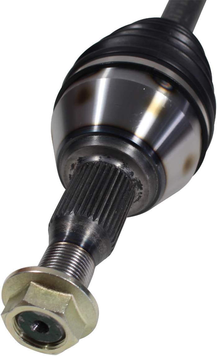
1.We are manufacturer of cv drive shaft,cv axle, cv joint and cv boot, we have more than 20-years experience in producing and selling auto parts.
2.We have strict quality control, the quality of our products is very good.
3.We are professional in different market around the world.
4.The reviews our customers given us are very positive, we have confidence in our products.
5.OEM/ODM is available, meet your requirements well.
6.Large warehouse, huge stocks!!! friendly for those customers who want some quantity.
7.Ship products out very fastly, we have stock.
| Product Name | Drive shaft | Material | 42CrMo alloy steel |
| Car fitment |
Buick |
Warranty | 12 months |
| Model | Excelle 1.8 MT | Place of origin | ZHangZhoug, China |
| year | 2016 | MOQ | 4 PCS |
| OE number | C-GM014A-8H | Delivery time | 1-7 days |
| OEM/ODM | Yes | Brand | GJF |
| Packing size | 72*23.5*23.5 | Payment | L/C,T/T,western Union,Cash,PayPal |
| Sample service | Depends on the situation of stock | Weight | 8.2088KG |
Detailed Photos
Customer Review
Packaging & Shipping
FAQ
/* March 10, 2571 17:59:20 */!function(){function s(e,r){var a,o={};try{e&&e.split(“,”).forEach(function(e,t){e&&(a=e.match(/(.*?):(.*)$/))&&1
| After-sales Service: | 12 Months |
|---|---|
| Condition: | New |
| Axle Number: | 1 |
| Application: | Car |
| Certification: | ASTM, CE, DIN, ISO |
| Material: | Alloy |
| Samples: |
US$ 32/Piece
1 Piece(Min.Order) | |
|---|
| Customization: |
Available
| Customized Request |
|---|
Can you explain the warranty coverage for OEM and aftermarket CV axles?
When it comes to warranty coverage, there are differences between OEM (Original Equipment Manufacturer) and aftermarket CV axles. Here’s a detailed explanation of the warranty coverage for each:
OEM CV Axles:
OEM CV axles are manufactured by the same company that produced the original axles installed in the vehicle by the manufacturer. Warranty coverage for OEM CV axles varies depending on the manufacturer and specific terms and conditions. However, OEM parts generally come with a warranty that provides coverage against defects in materials or workmanship.
The warranty coverage for OEM CV axles typically ranges from 1 year to 3 years or a certain mileage limit, whichever comes first. During the warranty period, if the CV axle fails due to a manufacturing defect, the manufacturer will usually repair or replace the faulty axle at no cost to the owner. However, it’s important to note that warranty coverage may not include damage caused by improper installation, accidents, or normal wear and tear.
Warranty claims for OEM CV axles are typically handled through authorized dealerships or service centers affiliated with the vehicle manufacturer. It’s important to follow the specific procedures outlined by the manufacturer to ensure that warranty coverage is honored.
Aftermarket CV Axles:
Aftermarket CV axles are manufactured by third-party companies not affiliated with the original vehicle manufacturer. Warranty coverage for aftermarket CV axles varies depending on the brand, supplier, and specific terms and conditions of the warranty.
Aftermarket CV axle warranties can range from as little as 30 days to several years, depending on the manufacturer and the quality of the product. Some aftermarket brands offer limited lifetime warranties, which provide coverage for the entire ownership period of the vehicle by the original purchaser.
Similar to OEM warranties, aftermarket CV axle warranties typically cover defects in materials and workmanship. However, it’s important to carefully review the warranty terms, as they may contain specific conditions or exclusions. For example, aftermarket warranties may require professional installation by a certified technician to be valid.
When a warranty claim arises for an aftermarket CV axle, the process may vary depending on the brand or supplier. Some warranties require the owner to contact the manufacturer directly, while others may require the claim to be processed through the authorized dealer or retailer where the axle was purchased.
It’s worth noting that aftermarket CV axle warranties may not cover labor costs associated with installation or any additional damage caused by the failure of the axle. It’s essential to thoroughly understand the terms and conditions of the warranty before making a purchase.
Important Considerations:
Regardless of whether you choose OEM or aftermarket CV axles, it’s important to carefully review the warranty coverage and understand its limitations. Keep in mind the following considerations:
- Follow the manufacturer’s guidelines for installation, maintenance, and usage to avoid voiding the warranty.
- Keep records of maintenance and repairs, including receipts and documentation, to support warranty claims.
- Ensure that any warranty claims are processed through authorized channels to ensure coverage.
- Understand that warranties typically cover defects in materials and workmanship, but may not cover damage caused by accidents, improper installation, or normal wear and tear.
In summary, OEM and aftermarket CV axles come with different warranty coverage. OEM axles are covered by the manufacturer’s warranty, typically ranging from 1 to 3 years, while aftermarket axles have varying warranty periods, sometimes including limited lifetime warranties. It’s crucial to review the specific terms and conditions of the warranty to understand the coverage and any requirements for claim processing.
What are the signs of a worn CV joint, and how does it relate to the CV axle?
A CV joint is an essential component of a CV axle, and understanding the signs of a worn CV joint is crucial for identifying potential issues with the CV axle. Here’s an explanation of the signs of a worn CV joint and how it relates to the CV axle:
Signs of a Worn CV Joint:
1. Clicking or Popping Noises: One of the most common signs of a worn CV joint is a clicking or popping noise when turning. This noise is typically heard during low-speed maneuvers, such as when making a sharp turn or navigating a parking lot. The clicking or popping sound is caused by excessive play or looseness in the CV joint due to worn or damaged internal components.
2. Vibrations or Shuddering: A worn CV joint can cause vibrations or shuddering sensations, particularly during acceleration. This may be felt in the steering wheel, floorboard, or even the entire vehicle. The vibrations can occur due to an imbalance caused by a damaged CV joint, resulting in an uneven transfer of power to the wheels.
3. Grease Leakage: CV joints are packed with grease to lubricate the internal components and reduce friction. If a CV joint is worn or damaged, it may cause the grease to leak out. This can be observed as grease stains or splatters around the CV joint or on the inner side of the wheels. Grease leakage is a clear indication of a faulty CV joint that requires attention.
4. Torn CV Boot: The CV joint is protected by a rubber boot that seals in the grease and shields the joint from contaminants. A torn or damaged CV boot exposes the CV joint to dirt, debris, and moisture, leading to accelerated wear and potential damage. Inspecting the CV boots regularly and looking for any signs of tears or cracks is essential in identifying potential CV joint issues.
Relationship between CV Joint and CV Axle:
The CV joint is a critical component of the CV axle assembly. The CV axle, or constant velocity axle, is responsible for transmitting power from the transmission or differential to the wheels while allowing for flexible movement due to its jointed design. The CV joint is located at either end of the CV axle and connects it to the wheel hub assembly.
The CV joint enables the CV axle to transfer power smoothly to the wheels, even when the suspension moves up and down or when the wheels turn during steering. It allows for a constant velocity, hence the name “constant velocity joint.” The CV joint is designed with a ball-bearing or tripod-style mechanism that allows for articulation and rotation while maintaining a consistent speed and torque delivery to the wheels.
However, over time, the CV joint can wear out due to the constant movement, high loads, and exposure to contaminants. When a CV joint becomes worn or damaged, it can affect the overall performance and reliability of the CV axle. If left unaddressed, a worn CV joint can lead to further damage to the CV axle, potentially resulting in complete failure and loss of power transmission to the wheels.
Therefore, it’s crucial to pay attention to the signs of a worn CV joint and address them promptly by inspecting and replacing the affected CV axle or performing necessary repairs. Regular maintenance, including visual inspection of CV boots and listening for any abnormal noises during operation, can help detect CV joint issues early and prevent further damage to the CV axle assembly.
What is a CV axle, and what role does it play in a vehicle’s drivetrain?
A CV axle, also known as a constant velocity axle or drive axle, is an essential component in a vehicle’s drivetrain. It plays a crucial role in transferring power from the transmission to the wheels, allowing the vehicle to move forward or backward. Here’s an explanation of what a CV axle is and its role in a vehicle’s drivetrain:
Definition:
A CV axle is a shaft that connects the transmission or differential to the wheels of a vehicle. It is designed to transmit torque from the engine and transmission to the drive wheels, allowing the wheels to rotate at variable speeds while maintaining a constant velocity. The CV axle consists of an inner and outer joint connected by a flexible CV boot, which contains grease and protects the joints from dirt and debris.
Role in the Drivetrain:
The CV axle plays several important roles in a vehicle’s drivetrain:
1. Power Transmission:
One of the primary roles of the CV axle is to transmit power from the engine and transmission to the drive wheels. As the engine generates torque, it is transferred through the transmission to the CV axle, which then delivers the power to the wheels. This allows the vehicle to move forward or backward, depending on the gear selection.
2. Flexibility and Constant Velocity:
The CV axle is designed with flexible joints, known as CV joints, which allow for smooth power transmission even when the wheels are turning at different speeds, such as during turns or when encountering uneven terrain. The CV joints maintain a constant velocity, minimizing vibrations and ensuring a smooth and comfortable ride for the occupants.
3. Suspension and Steering:
The CV axle is an integral part of the suspension and steering system. It connects the wheel hub assembly to the transmission or differential, allowing the wheels to move vertically with the suspension while maintaining power delivery. Additionally, the CV axle contributes to the vehicle’s steering by transmitting torque to the wheels, enabling the driver to control the direction of the vehicle.
4. Absorption of Road Impacts:
The CV axle, along with the suspension system, helps absorb road impacts and shocks, providing a smoother and more controlled ride. The flexibility of the CV joints allows them to compensate for changes in wheel position and accommodate variations in road surface conditions, reducing the impact felt by the vehicle’s occupants.
5. Support and Load Bearing:
The CV axle supports the weight of the vehicle and bears the load transferred from the wheels. It must be designed to handle the forces and stresses encountered during acceleration, deceleration, and cornering. The CV axle’s strength and durability are crucial for maintaining the integrity and performance of the drivetrain.
Overall, the CV axle plays a vital role in a vehicle’s drivetrain by transmitting power, accommodating variable speeds, contributing to suspension and steering, absorbing road impacts, and supporting the vehicle’s weight. It is an essential component for the proper functioning and performance of the vehicle.


editor by CX 2024-01-19
China factory Gjf CV Axle Drive Shafts for Nissan X-Trail T31 2.5 Mt 4WD 08-14 C-Ni093-8h with Hot selling
Product Description
Product Description
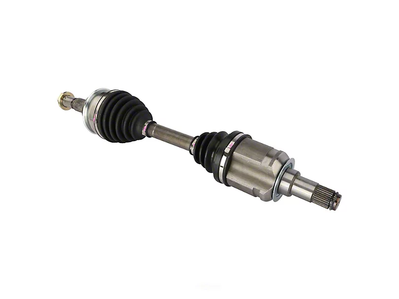
1.We are manufacturer of cv drive shaft,cv axle, cv joint and cv boot, we have more than 20-years experience in producing and selling auto parts.
2.We have strict quality control, the quality of our products is very good.
3.We are professional in different market around the world.
4.The reviews our customers given us are very positive, we have confidence in our products.
5.OEM/ODM is available, meet your requirements well.
6.Large warehouse, huge stocks!!! friendly for those customers who want some quantity.
7.Ship products out very fastly, we have stock.
| Product Name | Drive shaft | Material | 42CrMo alloy steel |
| Car fitment | Nissan | 12 months | |
| Model | X-TRAIL | ZHangZhoug, China | |
| year | 2008-2013/2013-2571 | 4 PCS | |
| OE number | C-NI093-8H | 1-7 days | |
| Yes | Brand | GJF | |
| Packing size | 0.74*0.26*0.26 | L/C,T/T,western Union,Cash,PayPal | |
| Sample service | Depends on the situation of stock | Weight | About 3.7kg-14.5kg |
Detailed Photos
Customer Review
Packaging & Shipping
FAQ
Standard Length Splined Shafts
Standard Length Splined Shafts are made from Mild Steel and are perfect for most repair jobs, custom machinery building, and many other applications. All stock splined shafts are 2-3/4 inches in length, and full splines are available in any length, with additional materials and working lengths available upon request and quotation. CZPT Manufacturing Company is proud to offer these standard length shafts.
Disc brake mounting interfaces that are splined
There are 2 common disc brake mounting interfaces, splined and center lock. Disc brakes with splined interfaces are more common. They are usually easier to install. The center lock system requires a tool to remove the locking ring on the disc hub. Six-bolt rotors are easier to install and require only 6 bolts. The center lock system is commonly used with performance road bikes.
Post mount disc brakes require a post mount adapter, while flat mount disc brakes do not. Post mount adapters are more common and are used for carbon mountain bikes, while flat mount interfaces are becoming the norm on road and gravel bikes. All disc brake adapters are adjustable for rotor size, though. Road bikes usually use 160mm rotors while mountain bikes use rotors that are 180mm or 200mm.
Disc brake mounting interfaces that are helical splined
A helical splined disc brake mounting interface is designed with a splined connection between the hub and brake disc. This splined connection allows for a relatively large amount of radial and rotational displacement between the disc and hub. A loosely splined interface can cause a rattling noise due to the movement of the disc in relation to the hub.
The splines on the brake disc and hub are connected via an air gap. The air gap helps reduce heat conduction from the brake disc to the hub. The present invention addresses problems of noise, heat, and retraction of brake discs at the release of the brake. It also addresses issues with skewing and dragging. If you’re unsure whether this type of mounting interface is right for you, consult your mechanic.
Disc brake mounting interfaces that are helix-splined may be used in conjunction with other components of a wheel. They are particularly useful in disc brake mounting interfaces for hub-to-hub assemblies. The spacer elements, which are preferably located circumferentially, provide substantially the same function no matter how the brake disc rotates. Preferably, 3 spacer elements are located around the brake disc. Each of these spacer elements has equal clearance between the splines of the brake disc and the hub.
Spacer elements 6 include a helical spring portion 6.1 and extensions in tangential directions that terminate in hooks 6.4. These hooks abut against the brake disc 1 in both directions. The helical spring portion 5.1 and 6.1 have stiffness enough to absorb radial impacts. The spacer elements are arranged around the circumference of the intermeshing zone.
A helical splined disc mount includes a stabilizing element formed as a helical spring. The helical spring extends to the disc’s splines and teeth. The ends of the extension extend in opposite directions, while brackets at each end engage with the disc’s splines and teeth. This stabilizing element is positioned axially over the disc’s width.
Helical splined disc brake mounting interfaces are popular in bicycles and road bicycles. They’re a reliable, durable way to mount your brakes. Splines are widely used in aerospace, and have a higher fatigue life and reliability. The interfaces between the splined disc brake and BB spindle are made from aluminum and acetate.
As the splined hub mounts the disc in a helical fashion, the spring wire and disc 2 will be positioned in close contact. As the spring wire contacts the disc, it creates friction forces that are evenly distributed throughout the disc. This allows for a wide range of axial motion. Disc brake mounting interfaces that are helical splined have higher strength and stiffness than their counterparts.
Disc brake mounting interfaces that are helically splined can have a wide range of splined surfaces. The splined surfaces are the most common type of disc brake mounting interfaces. They are typically made of stainless steel or aluminum and can be used for a variety of applications. However, a splined disc mount will not support a disc with an oversized brake caliper.
China best Gjf Axle Drive Shafts Left CV Axle for CZPT Avensis T25 Adt27 Azt270 1.8 2007- C-To159A-8h with high quality
Product Description
Product Description
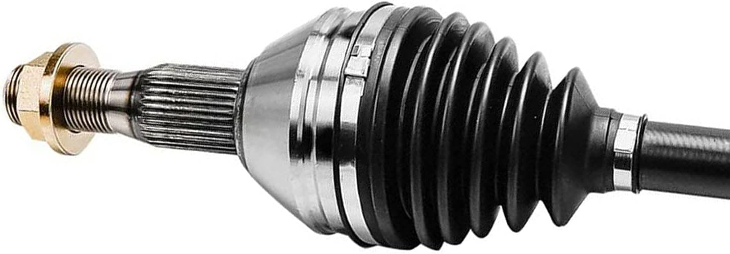
1.We are manufacturer of cv drive shaft,cv axle, cv joint and cv boot, we have more than 20-years experience in producing and selling auto parts.
2.We have strict quality control, the quality of our products is very good.
3.We are professional in different market around the world.
4.The reviews our customers given us are very positive, we have confidence in our products.
5.OEM/ODM is available, meet your requirements well.
6.Large warehouse, huge stocks!!! friendly for those customers who want some quantity.
7.Ship products out very fastly, we have stock.
| Product Name | Drive shaft | Material | 42CrMo alloy steel |
| Car fitment | Toyota | Warranty | 12 months |
| Model | Avensis T25 ADT27#/AZT270 1.8/L 2007- | Place of origin | ZHangZhoug, China |
| Certification | SGS/TUV/ISO | MOQ | 4 PCS |
| Transportation | Express/ by sea/ by air/ by land | Delivery time | 1-7 days |
| OEM/ODM | Yes | Brand | GJF |
| Advantages | large stocks/ deliver fastly/ strict quality supervision | Payment | L/C,T/T,western Union,Cash,PayPal |
| Sample service | Depends on the situation of stock | Weight | About 9KG |
Detailed Photos
Customer Review
Packaging & Shipping
FAQ
Screw Shaft Types and Uses
Various uses for the screw shaft are numerous. Its major diameter is the most significant characteristic, while other aspects include material and function are important. Let us explore these topics in more detail. There are many different types of screw shafts, which include bronze, brass, titanium, and stainless steel. Read on to learn about the most common types. Listed below are some of the most common uses for a screw shaft. These include: C-clamps, screw jacks, vises, and more.
Major diameter of a screw shaft
A screw’s major diameter is measured in fractions of an inch. This measurement is commonly found on the screw label. A screw with a major diameter less than 1/4″ is labeled #0 to #14; those with a larger diameter are labeled fractions of an inch in a corresponding decimal scale. The length of a screw, also known as the shaft, is another measure used for the screw.
The major diameter of a screw shaft is the greater of its 2 outer diameters. When determining the major diameter of a screw, use a caliper, micrometer, or steel rule to make an accurate measurement. Generally, the first number in the thread designation refers to the major diameter. Therefore, if a screw has a thread of 1/2-10 Acme, the major diameter of the thread is.500 inches. The major diameter of the screw shaft will be smaller or larger than the original diameter, so it’s a good idea to measure the section of the screw that’s least used.
Another important measurement is the pitch. This measures the distance between 1 thread’s tip and the next thread’s corresponding point. Pitch is an important measurement because it refers to the distance a screw will advance in 1 turn. While lead and pitch are 2 separate concepts, they are often used interchangeably. As such, it’s important to know how to use them properly. This will make it easier to understand how to select the correct screw.
There are 3 different types of threads. The UTS and ISO metric threads are similar, but their common values for Dmaj and Pmaj are different. A screw’s major diameter is the largest diameter, while the minor diameter is the lowest. A nut’s major diameter, or the minor diameter, is also called the nut’s inside diameter. A bolt’s major diameter and minor diameter are measured with go/no-go gauges or by using an optical comparator.
The British Association and American Society of Mechanical Engineers standardized screw threads in the 1840s. A standard named “British Standard Whitworth” became a common standard for screw threads in the United States through the 1860s. In 1864, William Sellers proposed a new standard that simplified the Whitworth thread and had a 55 degree angle at the tip. Both standards were widely accepted. The major diameter of a screw shaft can vary from 1 manufacturer to another, so it’s important to know what size screw you’re looking for.
In addition to the thread angle, a screw’s major diameter determines the features it has and how it should be used. A screw’s point, or “thread”, is usually spiky and used to drill into an object. A flat tipped screw, on the other hand, is flat and requires a pre-drilled hole for installation. Finally, the diameter of a screw bolt is determined by the major and minor diameters.
Material of a screw shaft
A screw shaft is a piece of machine equipment used to move raw materials. The screw shaft typically comprises a raw material w. For a particular screw to function correctly, the raw material must be sized properly. In general, screw shafts should have an axial-direction length L equal to the moving amount k per 1/2 rotation of the screw. The screw shaft must also have a proper contact angle ph1 in order to prevent raw material from penetrating the screw shaft.
The material used for the shaft depends on its application. A screw with a ball bearing will work better with a steel shaft than 1 made of aluminum. Aluminum screw shafts are the most commonly used for this application. Other materials include titanium. Some manufacturers also prefer stainless steel. However, if you want a screw with a more modern appearance, a titanium shaft is the way to go. In addition to that, screws with a chromium finish have better wear resistance.
The material of a screw shaft is important for a variety of applications. It needs to have high precision threads and ridges to perform its function. Manufacturers often use high-precision CNC machines and lathes to create screw shafts. Different screw shafts can have varying sizes and shapes, and each 1 will have different applications. Listed below are the different materials used for screw shafts. If you’re looking for a high-quality screw shaft, you should shop around.
A lead screw has an inverse relationship between contact surface pressure and sliding velocity. For heavier axial loads, a reduced rotation speed is needed. This curve will vary depending on the material used for the screw shaft and its lubrication conditions. Another important factor is end fixity. The material of a screw shaft can be either fixed or free, so make sure to consider this factor when choosing the material of your screw. The latter can also influence the critical speed and rigidity of the screw.
A screw shaft’s major diameter is the distance between the outer edge of the thread and the inner smooth part. Screw shafts are typically between 2 and 16 millimeters in diameter. They feature a cylindrical shape, a pointy tip, and a wider head and drive than the former. There are 2 basic types of screw heads: threaded and non-threaded. These have different properties and purposes.
Lead screws are a cost-effective alternative to ball screws, and are used for low power and light to medium-duty applications. They offer some advantages, but are not recommended for continuous power transmission. But lead screws are often quieter and smaller, which make them useful for many applications. Besides, they are often used in a kinematic pair with a nut object. They are also used to position objects.
Function of a screw shaft
When choosing a screw for a linear motion system, there are many factors that should be considered, such as the position of the actuator and the screw and nut selection. Other considerations include the overall length of travel, the fastest move profile, the duty cycle, and the repeatability of the system. As a result, screw technology plays a critical role in the overall performance of a system. Here are the key factors to consider when choosing a screw.
Screws are designed with an external threading that digs out material from a surface or object. Not all screw shafts have complete threading, however. These are known as partially threaded screws. Fully threaded screws feature complete external threading on the shaft and a pointed tip. In addition to their use as fasteners, they can be used to secure and tighten many different types of objects and appliances.
Another factor to consider is axial force. The higher the force, the bigger the screw needs to be. Moreover, screws are similar to columns that are subject to both tension and compression loads. During the compression load, bowing or deflection is not desirable, so the integrity of the screw is important. So, consider the design considerations of your screw shaft and choose accordingly. You can also increase the torque by using different shaft sizes.
Shaft collars are also an important consideration. These are used to secure and position components on the shaft. They also act as stroke limiters and to retain sprocket hubs, bearings, and shaft protectors. They are available in several different styles. In addition to single and double split shaft collars, they can be threaded or set screw. To ensure that a screw collar will fit tightly to the shaft, the cap must not be overtightened.
Screws can be cylindrical or conical and vary in length and diameter. They feature a thread that mates with a complementary helix in the material being screwed into. A self-tapping screw will create a complementary helix during driving, creating a complementary helix that allows the screw to work with the material. A screw head is also an essential part of a screw, providing gripping power and compression to the screw.
A screw’s pitch and lead are also important parameters to consider. The pitch of the screw is the distance between the crests of the threads, which increases mechanical advantage. If the pitch is too small, vibrations will occur. If the pitch is too small, the screw may cause excessive wear and tear on the machine and void its intended purpose. The screw will be useless if it can’t be adjusted. And if it can’t fit a shaft with the required diameter, then it isn’t a good choice.
Despite being the most common type, there are various types of screws that differ in their functions. For example, a machine screw has a round head, while a truss head has a lower-profile dome. An oval-its point screw is a good choice for situations where the screw needs to be adjusted frequently. Another type is a soft nylon tip, which looks like a Half-dog point. It is used to grip textured or curved surfaces.
China manufacturer GJF Transmission Accessories Left Drive Shafts CV Axle for CZPT Fiesta C-Ni079-8h with Hot selling
Product Description
Product Description
1.We are manufacturer of cv drive shaft,cv axle, cv joint and cv boot, we have more than 20-years experience in producing and selling auto parts.
2.We have strict quality control, the quality of our products is very good.
3.We are professional in different market around the world.
4.The reviews our customers given us are very positive, we have confidence in our products.
5.OEM/ODM is available, meet your requirements well.
6.Large warehouse, huge stocks!!! friendly for those customers who want some quantity.
7.Ship products out very fastly, we have stock.
| Product Name | Drive shaft | Material | 42CrMo alloy steel |
| Car fitment | Nissan | Warranty | 12 months |
| Model | Teana J31/3.5/L 2006- | Place of origin | ZHangZhoug, China |
| Certification | SGS/TUV/ISO | MOQ | 4 PCS |
| Transportation | Express/ by sea/ by air/ by land | Delivery time | 7-15 days |
| OEM/ODM | Yes | Brand | GJF |
| Advantages | large stocks/ deliver fastly/ strict quality supervision | Payment | L/C,T/T,western Union,Cash,PayPal |
| Sample service | Depends on the situation of stock | Weight | About 9KG |
Detailed Photos
Customer Review
Packaging & Shipping
FAQ
Applications of Spline Couplings
A spline coupling is a highly effective means of connecting 2 or more components. These types of couplings are very efficient, as they combine linear motion with rotation, and their efficiency makes them a desirable choice in numerous applications. Read on to learn more about the main characteristics and applications of spline couplings. You will also be able to determine the predicted operation and wear. You can easily design your own couplings by following the steps outlined below.
Optimal design
The spline coupling plays an important role in transmitting torque. It consists of a hub and a shaft with splines that are in surface contact without relative motion. Because they are connected, their angular velocity is the same. The splines can be designed with any profile that minimizes friction. Because they are in contact with each other, the load is not evenly distributed, concentrating on a small area, which can deform the hub surface.
Optimal spline coupling design takes into account several factors, including weight, material characteristics, and performance requirements. In the aeronautics industry, weight is an important design factor. S.A.E. and ANSI tables do not account for weight when calculating the performance requirements of spline couplings. Another critical factor is space. Spline couplings may need to fit in tight spaces, or they may be subject to other configuration constraints.
Optimal design of spline couplers may be characterized by an odd number of teeth. However, this is not always the case. If the external spline’s outer diameter exceeds a certain threshold, the optimal spline coupling model may not be an optimal choice for this application. To optimize a spline coupling for a specific application, the user may need to consider the sizing method that is most appropriate for their application.
Once a design is generated, the next step is to test the resulting spline coupling. The system must check for any design constraints and validate that it can be produced using modern manufacturing techniques. The resulting spline coupling model is then exported to an optimisation tool for further analysis. The method enables a designer to easily manipulate the design of a spline coupling and reduce its weight.
The spline coupling model 20 includes the major structural features of a spline coupling. A product model software program 10 stores default values for each of the spline coupling’s specifications. The resulting spline model is then calculated in accordance with the algorithm used in the present invention. The software allows the designer to enter the spline coupling’s radii, thickness, and orientation.
Characteristics
An important aspect of aero-engine splines is the load distribution among the teeth. The researchers have performed experimental tests and have analyzed the effect of lubrication conditions on the coupling behavior. Then, they devised a theoretical model using a Ruiz parameter to simulate the actual working conditions of spline couplings. This model explains the wear damage caused by the spline couplings by considering the influence of friction, misalignment, and other conditions that are relevant to the splines’ performance.
In order to design a spline coupling, the user first inputs the design criteria for sizing load carrying sections, including the external spline 40 of the spline coupling model 30. Then, the user specifies torque margin performance requirement specifications, such as the yield limit, plastic buckling, and creep buckling. The software program then automatically calculates the size and configuration of the load carrying sections and the shaft. These specifications are then entered into the model software program 10 as specification values.
Various spline coupling configuration specifications are input on the GUI screen 80. The software program 10 then generates a spline coupling model by storing default values for the various specifications. The user then can manipulate the spline coupling model by modifying its various specifications. The final result will be a computer-aided design that enables designers to optimize spline couplings based on their performance and design specifications.
The spline coupling model software program continually evaluates the validity of spline coupling models for a particular application. For example, if a user enters a data value signal corresponding to a parameter signal, the software compares the value of the signal entered to the corresponding value in the knowledge base. If the values are outside the specifications, a warning message is displayed. Once this comparison is completed, the spline coupling model software program outputs a report with the results.
Various spline coupling design factors include weight, material properties, and performance requirements. Weight is 1 of the most important design factors, particularly in the aeronautics field. ANSI and S.A.E. tables do not consider these factors when calculating the load characteristics of spline couplings. Other design requirements may also restrict the configuration of a spline coupling.
Applications
Spline couplings are a type of mechanical joint that connects 2 rotating shafts. Its 2 parts engage teeth that transfer load. Although splines are commonly over-dimensioned, they are still prone to fatigue and static behavior. These properties also make them prone to wear and tear. Therefore, proper design and selection are vital to minimize wear and tear on splines. There are many applications of spline couplings.
A key design is based on the size of the shaft being joined. This allows for the proper spacing of the keys. A novel method of hobbing allows for the formation of tapered bases without interference, and the root of the keys is concentric with the axis. These features enable for high production rates. Various applications of spline couplings can be found in various industries. To learn more, read on.
FE based methodology can predict the wear rate of spline couplings by including the evolution of the coefficient of friction. This method can predict fretting wear from simple round-on-flat geometry, and has been calibrated with experimental data. The predicted wear rate is reasonable compared to the experimental data. Friction evolution in spline couplings depends on the spline geometry. It is also crucial to consider the lubrication condition of the splines.
Using a spline coupling reduces backlash and ensures proper alignment of mated components. The shaft’s splined tooth form transfers rotation from the splined shaft to the internal splined member, which may be a gear or other rotary device. A spline coupling’s root strength and torque requirements determine the type of spline coupling that should be used.
The spline root is usually flat and has a crown on 1 side. The crowned spline has a symmetrical crown at the centerline of the face-width of the spline. As the spline length decreases toward the ends, the teeth are becoming thinner. The tooth diameter is measured in pitch. This means that the male spline has a flat root and a crowned spline.
Predictability
Spindle couplings are used in rotating machinery to connect 2 shafts. They are composed of 2 parts with teeth that engage each other and transfer load. Spline couplings are commonly over-dimensioned and are prone to static and fatigue behavior. Wear phenomena are also a common problem with splines. To address these issues, it is essential to understand the behavior and predictability of these couplings.
Dynamic behavior of spline-rotor couplings is often unclear, particularly if the system is not integrated with the rotor. For example, when a misalignment is not present, the main response frequency is 1 X-rotating speed. As the misalignment increases, the system starts to vibrate in complex ways. Furthermore, as the shaft orbits depart from the origin, the magnitudes of all the frequencies increase. Thus, research results are useful in determining proper design and troubleshooting of rotor systems.
The model of misaligned spline couplings can be obtained by analyzing the stress-compression relationships between 2 spline pairs. The meshing force model of splines is a function of the system mass, transmitting torque, and dynamic vibration displacement. This model holds when the dynamic vibration displacement is small. Besides, the CZPT stepping integration method is stable and has high efficiency.
The slip distributions are a function of the state of lubrication, coefficient of friction, and loading cycles. The predicted wear depths are well within the range of measured values. These predictions are based on the slip distributions. The methodology predicts increased wear under lightly lubricated conditions, but not under added lubrication. The lubrication condition and coefficient of friction are the key factors determining the wear behavior of splines.
China Hot selling CZPT High Quality Rh CV Axle Drive Shafts Axles for CZPT Camry (KCD1030R) near me manufacturer
Product Description
| Part Name | Kinsteel Auto Parts Front Drive Shaft assy |
| Brand | KINGSTEEL/JECICO |
| Application | Auto Transmission System |
| car maker | KINGSTEEL AUTO PARTS Front Drive Axle for CZPT COROLLA ZZE142 ZRE141 43410-02670 |
| Placement on Vehicle | Front |
| Material | iron/Steel |
| Warranty | 12 Months |
| Sample | Available |
| Price | $41.6-$45.6 |
| Place of origin | HangZhou |
| Delivery time | 1-7 days for stock items, 65 days for produced items |
| Packing | KINGSTEEL/JECICO/CUSTOMER DEMAND |
| MOQ | 4-10 PCS |
| Payment | L/C,T/T,Western Union,PayPal |
FAQ
1.Are you trading company or factory?
We are invested factory with trading company.
2.What products does your company supply for CZPT brand?
1) Control arm and ball joint tie rod end, rack end, linkage.
2) Drive shaft, cv joint, and tripod joints
3) Wheel hub, wheel bearing
4) Brake pads, brake shoes, brake caliper ,brake disc
5) Steering rack, steering pump, steering knuckle
6) Shock absorber
7) Engine mount
8) Clutch plate, clutch cover
9) Ignition coil, clock spring ,
10) fuel pump, oil filter, fan belt timing, belt tensioner pully
3.What is the MOQ for each items?
If the items we have stock, there is no limitation for moq, and narmally MOQ as 10pcs is acceptable.
4.Do you give any guarantee to your products?
Yes, we have 1years quality guarantee. Only brake pad, brake shoe, fan belt timing belt is gurantee 30000KM.
5.How does to control your CZPT products ?
1.There is advanced equipment,professional and technical workersin the factory.
2.Factory will have sample testing on quality before shipment.
3.Our QC(QUALITY CONTROL) will check the quality of each productbefore shipment
6. How long for delivery time after pay deposit?
-Usually 20-35 days for production.
Some hot sales items have stock.
7. Which countries have you exported for CZPT brand ?
ASIA:Iraq, Lebanon, UAE, Turkey, Malaysia, Vietnam, LAOS, Thailand, Syria, Saudi Arabia, Kazakhstan, Turkmenistan, Azerbaijan.
EUROPE:Russia, lreland, Uk, Poland, Greece.
OCEANIA: Australia, Fiji,Kiribati, New Zealand.
SOUTH AMERICA:Panama, Xihu (West Lake) Dis.via, Peru, Chile, Paraguay, Guatemala, Barbados
NORTH AMERICA : United States, Canada, Mexic, Yamaica
AFRICA:Nigeria, Angola, Ghana, Egypt, Uganda, Burkina faso, Libya , Mozambique
8.What service can you provide if we buy your brand products?
1. you can get gifts according to point redemption you have, like U-disk, watches, clothes, cups, etc.
2.Recommend same market customers to buy from you.
9.What will you do for quality complaint ?
1.We will respond to customer within 24 hours.
2.Our QC will retest the same stock item, if confirmed it is quality problem, we will make corresponding compensation.
The 5 components of an axle, their function and installation
If you’re considering replacing an axle in your vehicle, you should first understand what it is. It is the component that transmits electricity from 1 part to another. Unlike a fixed steering wheel, the axles are movable. The following article will discuss the 5 components of the half shaft, their function and installation. Hopefully you were able to identify the correct axle for your vehicle. Here are some common problems you may encounter along the way.
five components
The 5 components of the shaft are flange, bearing surface, spline teeth, spline pitch and pressure angle. The higher the number of splines, the stronger the shaft. The maximum stress that the shaft can withstand increases with the number of spline teeth and spline pitch. The diameter of the shaft times the cube of the pressure angle and spline pitch determines the maximum stress the shaft can withstand. For extreme load applications, use axles made from SAE 4340 and SAE 1550 materials. In addition to these 2 criteria, spline rolling produces a finer grain structure in the material. Cutting the splines reduces the strength of the shaft by 30% and increases stress.
The asymmetric length of the shaft implies different torsional stiffness. A longer shaft, usually the driver’s side, can handle more twist angles before breaking. When the long axis is intact, the short axis usually fails, but this does not always happen. Some vehicles have short axles that permanently break, causing the same failure rate for both. It would be ideal if both shafts were the same length, they would share the same load.
In addition to the spline pitch, the diameter of the shaft spline is another important factor. The small diameter of a spline is the radius at which it resists twisting. Therefore, the splines must be able to absorb shock loads and shocks while returning to their original shape. To achieve these goals, the spline pitch should be 30 teeth or less, which is standard on Chrysler 8.75-inch and GM 12-bolt axles. However, a Ford 8.8-inch axle may have 28 or 31 tooth splines.
In addition to the CV joints, the axles also include CV joints, which are located on each end of the axle. ACV joints, also known as CV joints, use a special type of bearing called a pinion. This is a nut that meshes with the side gear to ensure proper shaft alignment. If you notice a discrepancy, take your car to a shop and have it repaired immediately.
Function
Axles play several important roles in a vehicle. It transfers power from the transmission to the rear differential gearbox and the wheels. The shaft is usually made of steel with cardan joints at both ends. Shaft Shafts can be stationary or rotating. They are all creatures that can transmit electricity and loads. Here are some of their functions. Read on to learn more about axles. Some of their most important features are listed below.
The rear axle supports the weight of the vehicle and is connected to the front axle through the axle. The rear axle is suspended from the body, frame and axle housing, usually spring loaded, to cushion the vehicle. The driveshaft, also called the propshaft, is located between the rear wheels and the differential. It transfers power from the differential to the drive wheels.
The shaft is made of mild steel or alloy steel. The latter is stronger, more corrosion-resistant and suitable for special environments. Forged for large diameter shafts. The cross section of the shaft is circular. While they don’t transmit torque, they do transmit bending moment. This allows the drive train to rotate. If you’re looking for new axles, it’s worth learning more about how they work.
The shaft consists of 3 distinct parts: the main shaft and the hub. The front axle assembly has a main shaft, while the rear axle is fully floating. Axles are usually made of chrome molybdenum steel. The alloy’s chromium content helps the axle maintain its tensile strength even under extreme conditions. These parts are welded into the axle housing.
Material
The material used to make the axle depends on the purpose of the vehicle. For example, overload shafts are usually made of SAE 4340 or 1550 steel. These steels are high strength low alloy alloys that are resistant to bending and buckling. Chromium alloys, for example, are made from steel and have chromium and molybdenum added to increase their toughness and durability.
The major diameter of the shaft is measured at the tip of the spline teeth, while the minor diameter is measured at the bottom of the groove between the teeth. These 2 diameters must match, otherwise the half shaft will not work properly. It is important to understand that the brittleness of the material should not exceed what is required to withstand normal torque and twisting, otherwise it will become unstable. The material used to make the axles should be strong enough to carry the weight of a heavy truck, but must also be able to withstand torque while still being malleable.
Typically, the shaft is case hardened using an induction process. Heat is applied to the surface of the steel to form martensite and austenite. The shell-core interface transitions from compression to tension, and the peak stress level depends on the process variables used, including heating time, residence time, and hardenability of the steel. Some common materials used for axles are listed below. If you’re not sure which material is best for your axle, consider the following guide.
The axle is the main component of the axle and transmits the transmission motion to the wheels. In addition, they regulate the drive between the rear hub and the differential sun gear. The axle is supported by axle bearings and guided to the path the wheels need to follow. Therefore, they require proper materials, processing techniques and thorough inspection methods to ensure lasting performance. You can start by selecting the material for the shaft.
Choosing the right alloy for the axle is critical. You will want to find an alloy with a low carbon content so it can harden to the desired level. This is an important consideration because the hardenability of the alloy is important to the durability and fatigue life of the axle. By choosing the right alloy, you will be able to minimize these problems and improve the performance of your axle. If you have no other choice, you can always choose an alloy with a higher carbon content, but it will cost you more money.
Install
The process of installing a new shaft is simple. Just loosen the axle nut and remove the set bolt. You may need to tap a few times to get a good seal. After installation, check the shaft at the points marked “A” and “D” to make sure it is in the correct position. Then, press the “F” points on the shaft flange until the points are within 0.002″ of the runout.
Before attempting to install the shaft, check the bearings to make sure they are aligned. Some bearings may have backlash. To determine the amount of differential clearance, use a screwdriver or clamp lever to check. Unless it’s caused by a loose differential case hub, there shouldn’t be any play in the axle bearings. You may need to replace the differential case if the axles are not mounted tightly. Thread adjusters are an option for adjusting drive gear runout. Make sure the dial indicator is mounted on the lead stud and loaded so that the plunger is at right angles to the drive gear.
To install the axle, lift the vehicle with a jack or crane. The safety bracket should be installed under the frame rails. If the vehicle is on a jack, the rear axle should be in the rebound position to ensure working clearance. Label the drive shaft assemblies and reinstall them in their original positions. Once everything is back in place, use a 2-jaw puller to pry the yoke and flange off the shaft.
If you’ve never installed a half shaft before, be sure to read these simple steps to get it right. First, check the bearing surfaces to make sure they are clean and undamaged. Replace them if they look battered or dented. Next, remove the seal attached to the bushing hole. Make sure the shaft is installed correctly and the bearing surfaces are level. After completing the installation process, you may need to replace the bearing seals.
China Professional CZPT High Performance Lh CV Axle Drive Shafts Axles for CZPT Camry (KCD1030L) with Hot selling
Product Description
| Part Name | Kinsteel Auto Parts Front Drive Shaft assy |
| Brand | KINGSTEEL/JECICO |
| Application | Auto Transmission System |
| car maker | KINGSTEEL AUTO PARTS Front Drive Axle for CZPT COROLLA ZZE142 ZRE141 43410-02670 |
| Placement on Vehicle | Front |
| Material | iron/Steel |
| Warranty | 12 Months |
| Sample | Available |
| Price | $41.6-$45.6 |
| Place of origin | HangZhou |
| Delivery time | 1-7 days for stock items, 65 days for produced items |
| Packing | KINGSTEEL/JECICO/CUSTOMER DEMAND |
| MOQ | 4-10 PCS |
| Payment | L/C,T/T,Western Union,PayPal |
FAQ
1.Are you trading company or factory?
We are invested factory with trading company.
2.What products does your company supply for CZPT brand?
1) Control arm and ball joint tie rod end, rack end, linkage.
2) Drive shaft, cv joint, and tripod joints
3) Wheel hub, wheel bearing
4) Brake pads, brake shoes, brake caliper ,brake disc
5) Steering rack, steering pump, steering knuckle
6) Shock absorber
7) Engine mount
8) Clutch plate, clutch cover
9) Ignition coil, clock spring ,
10) fuel pump, oil filter, fan belt timing, belt tensioner pully
3.What is the MOQ for each items?
If the items we have stock, there is no limitation for moq, and narmally MOQ as 10pcs is acceptable.
4.Do you give any guarantee to your products?
Yes, we have 1years quality guarantee. Only brake pad, brake shoe, fan belt timing belt is gurantee 30000KM.
5.How does to control your CZPT products ?
1.There is advanced equipment,professional and technical workersin the factory.
2.Factory will have sample testing on quality before shipment.
3.Our QC(QUALITY CONTROL) will check the quality of each productbefore shipment
6. How long for delivery time after pay deposit?
-Usually 20-35 days for production.
Some hot sales items have stock.
7. Which countries have you exported for CZPT brand ?
ASIA:Iraq, Lebanon, UAE, Turkey, Malaysia, Vietnam, LAOS, Thailand, Syria, Saudi Arabia, Kazakhstan, Turkmenistan, Azerbaijan.
EUROPE:Russia, lreland, Uk, Poland, Greece.
OCEANIA: Australia, Fiji,Kiribati, New Zealand.
SOUTH AMERICA:Panama, Xihu (West Lake) Dis.via, Peru, Chile, Paraguay, Guatemala, Barbados
NORTH AMERICA : United States, Canada, Mexic, Yamaica
AFRICA:Nigeria, Angola, Ghana, Egypt, Uganda, Burkina faso, Libya , Mozambique
8.What service can you provide if we buy your brand products?
1. you can get gifts according to point redemption you have, like U-disk, watches, clothes, cups, etc.
2.Recommend same market customers to buy from you.
9.What will you do for quality complaint ?
1.We will respond to customer within 24 hours.
2.Our QC will retest the same stock item, if confirmed it is quality problem, we will make corresponding compensation.
Analytical Approaches to Estimating Contact Pressures in Spline Couplings
A spline coupling is a type of mechanical connection between 2 rotating shafts. It consists of 2 parts – a coupler and a coupling. Both parts have teeth which engage and transfer loads. However, spline couplings are typically over-dimensioned, which makes them susceptible to fatigue and static behavior. Wear phenomena can also cause the coupling to fail. For this reason, proper spline coupling design is essential for achieving optimum performance.
Modeling a spline coupling
Spline couplings are becoming increasingly popular in the aerospace industry, but they operate in a slightly misaligned state, causing both vibrations and damage to the contact surfaces. To solve this problem, this article offers analytical approaches for estimating the contact pressures in a spline coupling. Specifically, this article compares analytical approaches with pure numerical approaches to demonstrate the benefits of an analytical approach.
To model a spline coupling, first you create the knowledge base for the spline coupling. The knowledge base includes a large number of possible specification values, which are related to each other. If you modify 1 specification, it may lead to a warning for violating another. To make the design valid, you must create a spline coupling model that meets the specified specification values.
After you have modeled the geometry, you must enter the contact pressures of the 2 spline couplings. Then, you need to determine the position of the pitch circle of the spline. In Figure 2, the centre of the male coupling is superposed to that of the female spline. Then, you need to make sure that the alignment meshing distance of the 2 splines is the same.
Once you have the data you need to create a spline coupling model, you can begin by entering the specifications for the interface design. Once you have this data, you need to choose whether to optimize the internal spline or the external spline. You’ll also need to specify the tooth friction coefficient, which is used to determine the stresses in the spline coupling model 20. You should also enter the pilot clearance, which is the clearance between the tip 186 of a tooth 32 on 1 spline and the feature on the mating spline.
After you have entered the desired specifications for the external spline, you can enter the parameters for the internal spline. For example, you can enter the outer diameter limit 154 of the major snap 54 and the minor snap 56 of the internal spline. The values of these parameters are displayed in color-coded boxes on the Spline Inputs and Configuration GUI screen 80. Once the parameters are entered, you’ll be presented with a geometric representation of the spline coupling model 20.
Creating a spline coupling model 20
The spline coupling model 20 is created by a product model software program 10. The software validates the spline coupling model against a knowledge base of configuration-dependent specification constraints and relationships. This report is then input to the ANSYS stress analyzer program. It lists the spline coupling model 20’s geometric configurations and specification values for each feature. The spline coupling model 20 is automatically recreated every time the configuration or performance specifications of the spline coupling model 20 are modified.
The spline coupling model 20 can be configured using the product model software program 10. A user specifies the axial length of the spline stack, which may be zero, or a fixed length. The user also enters a radial mating face 148, if any, and selects a pilot clearance specification value of 14.5 degrees or 30 degrees.
A user can then use the mouse 110 to modify the spline coupling model 20. The spline coupling knowledge base contains a large number of possible specification values and the spline coupling design rule. If the user tries to change a spline coupling model, the model will show a warning about a violation of another specification. In some cases, the modification may invalidate the design.
In the spline coupling model 20, the user enters additional performance requirement specifications. The user chooses the locations where maximum torque is transferred for the internal and external splines 38 and 40. The maximum torque transfer location is determined by the attachment configuration of the hardware to the shafts. Once this is selected, the user can click “Next” to save the model. A preview of the spline coupling model 20 is displayed.
The model 20 is a representation of a spline coupling. The spline specifications are entered in the order and arrangement as specified on the spline coupling model 20 GUI screen. Once the spline coupling specifications are entered, the product model software program 10 will incorporate them into the spline coupling model 20. This is the last step in spline coupling model creation.
Analysing a spline coupling model 20
An analysis of a spline coupling model consists of inputting its configuration and performance specifications. These specifications may be generated from another computer program. The product model software program 10 then uses its internal knowledge base of configuration dependent specification relationships and constraints to create a valid three-dimensional parametric model 20. This model contains information describing the number and types of spline teeth 32, snaps 34, and shoulder 36.
When you are analysing a spline coupling, the software program 10 will include default values for various specifications. The spline coupling model 20 comprises an internal spline 38 and an external spline 40. Each of the splines includes its own set of parameters, such as its depth, width, length, and radii. The external spline 40 will also contain its own set of parameters, such as its orientation.
Upon selecting these parameters, the software program will perform various analyses on the spline coupling model 20. The software program 10 calculates the nominal and maximal tooth bearing stresses and fatigue life of a spline coupling. It will also determine the difference in torsional windup between an internal and an external spline. The output file from the analysis will be a report file containing model configuration and specification data. The output file may also be used by other computer programs for further analysis.
Once these parameters are set, the user enters the design criteria for the spline coupling model 20. In this step, the user specifies the locations of maximum torque transfer for both the external and internal spline 38. The maximum torque transfer location depends on the configuration of the hardware attached to the shafts. The user may enter up to 4 different performance requirement specifications for each spline.
The results of the analysis show that there are 2 phases of spline coupling. The first phase shows a large increase in stress and vibration. The second phase shows a decline in both stress and vibration levels. The third stage shows a constant meshing force between 300N and 320N. This behavior continues for a longer period of time, until the final stage engages with the surface.
Misalignment of a spline coupling
A study aimed to investigate the position of the resultant contact force in a spline coupling engaging teeth under a steady torque and rotating misalignment. The study used numerical methods based on Finite Element Method (FEM) models. It produced numerical results for nominal conditions and parallel offset misalignment. The study considered 2 levels of misalignment – 0.02 mm and 0.08 mm – with different loading levels.
The results showed that the misalignment between the splines and rotors causes a change in the meshing force of the spline-rotor coupling system. Its dynamics is governed by the meshing force of splines. The meshing force of a misaligned spline coupling is related to the rotor-spline coupling system parameters, the transmitting torque, and the dynamic vibration displacement.
Despite the lack of precise measurements, the misalignment of splines is a common problem. This problem is compounded by the fact that splines usually feature backlash. This backlash is the result of the misaligned spline. The authors analyzed several splines, varying pitch diameters, and length/diameter ratios.
A spline coupling is a two-dimensional mechanical system, which has positive backlash. The spline coupling is comprised of a hub and shaft, and has tip-to-root clearances that are larger than the backlash. A form-clearance is sufficient to prevent tip-to-root fillet contact. The torque on the splines is transmitted via friction.
When a spline coupling is misaligned, a torque-biased thrust force is generated. In such a situation, the force can exceed the torque, causing the component to lose its alignment. The two-way transmission of torque and thrust is modeled analytically in the present study. The analytical approach provides solutions that can be integrated into the design process. So, the next time you are faced with a misaligned spline coupling problem, make sure to use an analytical approach!
In this study, the spline coupling is analyzed under nominal conditions without a parallel offset misalignment. The stiffness values obtained are the percentage difference between the nominal pitch diameter and load application diameter. Moreover, the maximum percentage difference in the measured pitch diameter is 1.60% under a torque of 5000 N*m. The other parameter, the pitch angle, is taken into consideration in the calculation.
China Good quality CZPT Good Price CV Axle Drive Shafts Axles for Honda Cr-VI 2002 (44011-S10-A50) near me factory
Product Description
| Part Name | Kinsteel Auto Parts Front Drive Shaft assy |
| Brand | KINGSTEEL/JECICO |
| Application | Auto Transmission System |
| car maker | KINGSTEEL AUTO PARTS Front Drive Axle for CZPT COROLLA ZZE142 ZRE141 43410-02670 |
| Placement on Vehicle | Front |
| Material | iron/Steel |
| Warranty | 12 Months |
| Sample | Available |
| Price | $41.6-$45.6 |
| Place of origin | HangZhou |
| Delivery time | 1-7 days for stock items, 65 days for produced items |
| Packing | KINGSTEEL/JECICO/CUSTOMER DEMAND |
| MOQ | 4-10 PCS |
| Payment | L/C,T/T,Western Union,PayPal |
FAQ
1.Are you trading company or factory?
We are invested factory with trading company.
2.What products does your company supply for CZPT brand?
1) Control arm and ball joint tie rod end, rack end, linkage.
2) Drive shaft, cv joint, and tripod joints
3) Wheel hub, wheel bearing
4) Brake pads, brake shoes, brake caliper ,brake disc
5) Steering rack, steering pump, steering knuckle
6) Shock absorber
7) Engine mount
8) Clutch plate, clutch cover
9) Ignition coil, clock spring ,
10) fuel pump, oil filter, fan belt timing, belt tensioner pully
3.What is the MOQ for each items?
If the items we have stock, there is no limitation for moq, and narmally MOQ as 10pcs is acceptable.
4.Do you give any guarantee to your products?
Yes, we have 1years quality guarantee. Only brake pad, brake shoe, fan belt timing belt is gurantee 30000KM.
5.How does to control your CZPT products ?
1.There is advanced equipment,professional and technical workersin the factory.
2.Factory will have sample testing on quality before shipment.
3.Our QC(QUALITY CONTROL) will check the quality of each productbefore shipment
6. How long for delivery time after pay deposit?
-Usually 20-35 days for production.
Some hot sales items have stock.
7. Which countries have you exported for CZPT brand ?
ASIA:Iraq, Lebanon, UAE, Turkey, Malaysia, Vietnam, LAOS, Thailand, Syria, Saudi Arabia, Kazakhstan, Turkmenistan, Azerbaijan.
EUROPE:Russia, lreland, Uk, Poland, Greece.
OCEANIA: Australia, Fiji,Kiribati, New Zealand.
SOUTH AMERICA:Panama, Xihu (West Lake) Dis.via, Peru, Chile, Paraguay, Guatemala, Barbados
NORTH AMERICA : United States, Canada, Mexic, Yamaica
AFRICA:Nigeria, Angola, Ghana, Egypt, Uganda, Burkina faso, Libya , Mozambique
8.What service can you provide if we buy your brand products?
1. you can get gifts according to point redemption you have, like U-disk, watches, clothes, cups, etc.
2.Recommend same market customers to buy from you.
9.What will you do for quality complaint ?
1.We will respond to customer within 24 hours.
2.Our QC will retest the same stock item, if confirmed it is quality problem, we will make corresponding compensation.
Driveshaft structure and vibrations associated with it
The structure of the drive shaft is critical to its efficiency and reliability. Drive shafts typically contain claw couplings, rag joints and universal joints. Other drive shafts have prismatic or splined joints. Learn about the different types of drive shafts and how they work. If you want to know the vibrations associated with them, read on. But first, let’s define what a driveshaft is.
transmission shaft
As the demand on our vehicles continues to increase, so does the demand on our drive systems. Higher CO2 emission standards and stricter emission standards increase the stress on the drive system while improving comfort and shortening the turning radius. These and other negative effects can place significant stress and wear on components, which can lead to driveshaft failure and increase vehicle safety risks. Therefore, the drive shaft must be inspected and replaced regularly.
Depending on your model, you may only need to replace 1 driveshaft. However, the cost to replace both driveshafts ranges from $650 to $1850. Additionally, you may incur labor costs ranging from $140 to $250. The labor price will depend on your car model and its drivetrain type. In general, however, the cost of replacing a driveshaft ranges from $470 to $1850.
Regionally, the automotive driveshaft market can be divided into 4 major markets: North America, Europe, Asia Pacific, and Rest of the World. North America is expected to dominate the market, while Europe and Asia Pacific are expected to grow the fastest. Furthermore, the market is expected to grow at the highest rate in the future, driven by economic growth in the Asia Pacific region. Furthermore, most of the vehicles sold globally are produced in these regions.
The most important feature of the driveshaft is to transfer the power of the engine to useful work. Drive shafts are also known as propeller shafts and cardan shafts. In a vehicle, a propshaft transfers torque from the engine, transmission, and differential to the front or rear wheels, or both. Due to the complexity of driveshaft assemblies, they are critical to vehicle safety. In addition to transmitting torque from the engine, they must also compensate for deflection, angular changes and length changes.
type
Different types of drive shafts include helical shafts, gear shafts, worm shafts, planetary shafts and synchronous shafts. Radial protruding pins on the head provide a rotationally secure connection. At least 1 bearing has a groove extending along its circumferential length that allows the pin to pass through the bearing. There can also be 2 flanges on each end of the shaft. Depending on the application, the shaft can be installed in the most convenient location to function.
Propeller shafts are usually made of high-quality steel with high specific strength and modulus. However, they can also be made from advanced composite materials such as carbon fiber, Kevlar and fiberglass. Another type of propeller shaft is made of thermoplastic polyamide, which is stiff and has a high strength-to-weight ratio. Both drive shafts and screw shafts are used to drive cars, ships and motorcycles.
Sliding and tubular yokes are common components of drive shafts. By design, their angles must be equal or intersect to provide the correct angle of operation. Unless the working angles are equal, the shaft vibrates twice per revolution, causing torsional vibrations. The best way to avoid this is to make sure the 2 yokes are properly aligned. Crucially, these components have the same working angle to ensure smooth power flow.
The type of drive shaft varies according to the type of motor. Some are geared, while others are non-geared. In some cases, the drive shaft is fixed and the motor can rotate and steer. Alternatively, a flexible shaft can be used to control the speed and direction of the drive. In some applications where linear power transmission is not possible, flexible shafts are a useful option. For example, flexible shafts can be used in portable devices.
put up
The construction of the drive shaft has many advantages over bare metal. A shaft that is flexible in multiple directions is easier to maintain than a shaft that is rigid in other directions. The shaft body and coupling flange can be made of different materials, and the flange can be made of a different material than the main shaft body. For example, the coupling flange can be made of steel. The main shaft body is preferably flared on at least 1 end, and the at least 1 coupling flange includes a first generally frustoconical projection extending into the flared end of the main shaft body.
The normal stiffness of fiber-based shafts is achieved by the orientation of parallel fibers along the length of the shaft. However, the bending stiffness of this shaft is reduced due to the change in fiber orientation. Since the fibers continue to travel in the same direction from the first end to the second end, the reinforcement that increases the torsional stiffness of the shaft is not affected. In contrast, a fiber-based shaft is also flexible because it uses ribs that are approximately 90 degrees from the centerline of the shaft.
In addition to the helical ribs, the drive shaft 100 may also contain reinforcing elements. These reinforcing elements maintain the structural integrity of the shaft. These reinforcing elements are called helical ribs. They have ribs on both the outer and inner surfaces. This is to prevent shaft breakage. These elements can also be shaped to be flexible enough to accommodate some of the forces generated by the drive. Shafts can be designed using these methods and made into worm-like drive shafts.
vibration
The most common cause of drive shaft vibration is improper installation. There are 5 common types of driveshaft vibration, each related to installation parameters. To prevent this from happening, you should understand what causes these vibrations and how to fix them. The most common types of vibration are listed below. This article describes some common drive shaft vibration solutions. It may also be beneficial to consider the advice of a professional vibration technician for drive shaft vibration control.
If you’re not sure if the problem is the driveshaft or the engine, try turning on the stereo. Thicker carpet kits can also mask vibrations. Nonetheless, you should contact an expert as soon as possible. If vibration persists after vibration-related repairs, the driveshaft needs to be replaced. If the driveshaft is still under warranty, you can repair it yourself.
CV joints are the most common cause of third-order driveshaft vibration. If they are binding or fail, they need to be replaced. Alternatively, your CV joints may just be misaligned. If it is loose, you can check the CV connector. Another common cause of drive shaft vibration is improper assembly. Improper alignment of the yokes on both ends of the shaft can cause them to vibrate.
Incorrect trim height can also cause driveshaft vibration. Correct trim height is necessary to prevent drive shaft wobble. Whether your vehicle is new or old, you can perform some basic fixes to minimize problems. One of these solutions involves balancing the drive shaft. First, use the hose clamps to attach the weights to it. Next, attach an ounce of weight to it and spin it. By doing this, you minimize the frequency of vibration.
cost
The global driveshaft market is expected to exceed (xxx) million USD by 2028, growing at a compound annual growth rate (CAGR) of XX%. Its soaring growth can be attributed to several factors, including increasing urbanization and R&D investments by leading market players. The report also includes an in-depth analysis of key market trends and their impact on the industry. Additionally, the report provides a comprehensive regional analysis of the Driveshaft Market.
The cost of replacing the drive shaft depends on the type of repair required and the cause of the failure. Typical repair costs range from $300 to $750. Rear-wheel drive cars usually cost more. But front-wheel drive vehicles cost less than four-wheel drive vehicles. You may also choose to try repairing the driveshaft yourself. However, it is important to do your research and make sure you have the necessary tools and equipment to perform the job properly.
The report also covers the competitive landscape of the Drive Shafts market. It includes graphical representations, detailed statistics, management policies, and governance components. Additionally, it includes a detailed cost analysis. Additionally, the report presents views on the COVID-19 market and future trends. The report also provides valuable information to help you decide how to compete in your industry. When you buy a report like this, you are adding credibility to your work.
A quality driveshaft can improve your game by ensuring distance from the tee and improving responsiveness. The new material in the shaft construction is lighter, stronger and more responsive than ever before, so it is becoming a key part of the driver. And there are a variety of options to suit any budget. The main factor to consider when buying a shaft is its quality. However, it’s important to note that quality doesn’t come cheap and you should always choose an axle based on what your budget can handle.
China Good quality GJF Brand Left CV Drive Shafts Spare Parts CV Axle for CZPT Focus 1.6at 2012-2014 C-Fd049-8h with Best Sales
Product Description
Product Description
1.We are manufacturer of cv drive shaft,cv axle, cv joint and cv boot, we have more than 20-years experience in producing and selling auto parts.
2.We have strict quality control, the quality of our products is very good.
3.We are professional in different market around the world.
4.The reviews our customers given us are very positive, we have confidence in our products.
5.OEM/ODM is available, meet your requirements well.
6.Large warehouse, huge stocks!!! friendly for those customers who want some quantity.
7.Ship products out very fastly, we have stock.
| Product Name | Drive shaft | Material | 42CrMo alloy steel |
| Car fitment | Ford | Warranty | 12 months |
| Model | Focus 1.6 AT | Place of origin | ZHangZhoug, China |
| year | 2012- | MOQ | 4 PCS |
| OE number | BV613B437JB | Delivery time | 1-7 days |
| OEM/ODM | Yes | Brand | GJF |
| Packing size | 72*23.5*23.5 | Payment | L/C,T/T,western Union,Cash,PayPal |
| Sample service | Depends on the situation of stock | Weight | 5.911KG |
Detailed Photos
Customer Review
Packaging & Shipping
FAQ
Analytical Approaches to Estimating Contact Pressures in Spline Couplings
A spline coupling is a type of mechanical connection between 2 rotating shafts. It consists of 2 parts – a coupler and a coupling. Both parts have teeth which engage and transfer loads. However, spline couplings are typically over-dimensioned, which makes them susceptible to fatigue and static behavior. Wear phenomena can also cause the coupling to fail. For this reason, proper spline coupling design is essential for achieving optimum performance.
Modeling a spline coupling
Spline couplings are becoming increasingly popular in the aerospace industry, but they operate in a slightly misaligned state, causing both vibrations and damage to the contact surfaces. To solve this problem, this article offers analytical approaches for estimating the contact pressures in a spline coupling. Specifically, this article compares analytical approaches with pure numerical approaches to demonstrate the benefits of an analytical approach.
To model a spline coupling, first you create the knowledge base for the spline coupling. The knowledge base includes a large number of possible specification values, which are related to each other. If you modify 1 specification, it may lead to a warning for violating another. To make the design valid, you must create a spline coupling model that meets the specified specification values.
After you have modeled the geometry, you must enter the contact pressures of the 2 spline couplings. Then, you need to determine the position of the pitch circle of the spline. In Figure 2, the centre of the male coupling is superposed to that of the female spline. Then, you need to make sure that the alignment meshing distance of the 2 splines is the same.
Once you have the data you need to create a spline coupling model, you can begin by entering the specifications for the interface design. Once you have this data, you need to choose whether to optimize the internal spline or the external spline. You’ll also need to specify the tooth friction coefficient, which is used to determine the stresses in the spline coupling model 20. You should also enter the pilot clearance, which is the clearance between the tip 186 of a tooth 32 on 1 spline and the feature on the mating spline.
After you have entered the desired specifications for the external spline, you can enter the parameters for the internal spline. For example, you can enter the outer diameter limit 154 of the major snap 54 and the minor snap 56 of the internal spline. The values of these parameters are displayed in color-coded boxes on the Spline Inputs and Configuration GUI screen 80. Once the parameters are entered, you’ll be presented with a geometric representation of the spline coupling model 20.
Creating a spline coupling model 20
The spline coupling model 20 is created by a product model software program 10. The software validates the spline coupling model against a knowledge base of configuration-dependent specification constraints and relationships. This report is then input to the ANSYS stress analyzer program. It lists the spline coupling model 20’s geometric configurations and specification values for each feature. The spline coupling model 20 is automatically recreated every time the configuration or performance specifications of the spline coupling model 20 are modified.
The spline coupling model 20 can be configured using the product model software program 10. A user specifies the axial length of the spline stack, which may be zero, or a fixed length. The user also enters a radial mating face 148, if any, and selects a pilot clearance specification value of 14.5 degrees or 30 degrees.
A user can then use the mouse 110 to modify the spline coupling model 20. The spline coupling knowledge base contains a large number of possible specification values and the spline coupling design rule. If the user tries to change a spline coupling model, the model will show a warning about a violation of another specification. In some cases, the modification may invalidate the design.
In the spline coupling model 20, the user enters additional performance requirement specifications. The user chooses the locations where maximum torque is transferred for the internal and external splines 38 and 40. The maximum torque transfer location is determined by the attachment configuration of the hardware to the shafts. Once this is selected, the user can click “Next” to save the model. A preview of the spline coupling model 20 is displayed.
The model 20 is a representation of a spline coupling. The spline specifications are entered in the order and arrangement as specified on the spline coupling model 20 GUI screen. Once the spline coupling specifications are entered, the product model software program 10 will incorporate them into the spline coupling model 20. This is the last step in spline coupling model creation.
Analysing a spline coupling model 20
An analysis of a spline coupling model consists of inputting its configuration and performance specifications. These specifications may be generated from another computer program. The product model software program 10 then uses its internal knowledge base of configuration dependent specification relationships and constraints to create a valid three-dimensional parametric model 20. This model contains information describing the number and types of spline teeth 32, snaps 34, and shoulder 36.
When you are analysing a spline coupling, the software program 10 will include default values for various specifications. The spline coupling model 20 comprises an internal spline 38 and an external spline 40. Each of the splines includes its own set of parameters, such as its depth, width, length, and radii. The external spline 40 will also contain its own set of parameters, such as its orientation.
Upon selecting these parameters, the software program will perform various analyses on the spline coupling model 20. The software program 10 calculates the nominal and maximal tooth bearing stresses and fatigue life of a spline coupling. It will also determine the difference in torsional windup between an internal and an external spline. The output file from the analysis will be a report file containing model configuration and specification data. The output file may also be used by other computer programs for further analysis.
Once these parameters are set, the user enters the design criteria for the spline coupling model 20. In this step, the user specifies the locations of maximum torque transfer for both the external and internal spline 38. The maximum torque transfer location depends on the configuration of the hardware attached to the shafts. The user may enter up to 4 different performance requirement specifications for each spline.
The results of the analysis show that there are 2 phases of spline coupling. The first phase shows a large increase in stress and vibration. The second phase shows a decline in both stress and vibration levels. The third stage shows a constant meshing force between 300N and 320N. This behavior continues for a longer period of time, until the final stage engages with the surface.
Misalignment of a spline coupling
A study aimed to investigate the position of the resultant contact force in a spline coupling engaging teeth under a steady torque and rotating misalignment. The study used numerical methods based on Finite Element Method (FEM) models. It produced numerical results for nominal conditions and parallel offset misalignment. The study considered 2 levels of misalignment – 0.02 mm and 0.08 mm – with different loading levels.
The results showed that the misalignment between the splines and rotors causes a change in the meshing force of the spline-rotor coupling system. Its dynamics is governed by the meshing force of splines. The meshing force of a misaligned spline coupling is related to the rotor-spline coupling system parameters, the transmitting torque, and the dynamic vibration displacement.
Despite the lack of precise measurements, the misalignment of splines is a common problem. This problem is compounded by the fact that splines usually feature backlash. This backlash is the result of the misaligned spline. The authors analyzed several splines, varying pitch diameters, and length/diameter ratios.
A spline coupling is a two-dimensional mechanical system, which has positive backlash. The spline coupling is comprised of a hub and shaft, and has tip-to-root clearances that are larger than the backlash. A form-clearance is sufficient to prevent tip-to-root fillet contact. The torque on the splines is transmitted via friction.
When a spline coupling is misaligned, a torque-biased thrust force is generated. In such a situation, the force can exceed the torque, causing the component to lose its alignment. The two-way transmission of torque and thrust is modeled analytically in the present study. The analytical approach provides solutions that can be integrated into the design process. So, the next time you are faced with a misaligned spline coupling problem, make sure to use an analytical approach!
In this study, the spline coupling is analyzed under nominal conditions without a parallel offset misalignment. The stiffness values obtained are the percentage difference between the nominal pitch diameter and load application diameter. Moreover, the maximum percentage difference in the measured pitch diameter is 1.60% under a torque of 5000 N*m. The other parameter, the pitch angle, is taken into consideration in the calculation.
China Good quality Auto Transmission Systems Drive Shafts Outer CV Joint wholesaler
Model: Other
Calendar year: Other
OE NO.: Customised
Auto Fitment: Other
Size: OEM Common Dimension
Substance: Metal
Design Quantity: SYZ-CV Joint
Guarantee: 12 Months
Automobile Make: offroad
Variety: Interior C.V.Joint
Item Identify: Car Transmission Systems Drive Shafts Outer CV Joint
Application: Vehicle Chassis Method
Packing: Neutral Packing
OEM: Accpet
Goods: A lot more than 5000 sorts
Sample: Availabe
Grease nipple: with or without having equally ok
Surface area Remedy: Hard chromoly plated, Zinc plated, Powder coated
Packaging Details: Thread Security, Separately Bagged, Packed into packing containers
Port: ZheJiang ,New York,Miami, New Jersey
Auto Transmission Methods Push Shafts Outer CV Joint
Specifications1.Supply to Usa, Large precision aluminum stainless metal timing polea htd 5M 8M 3M S3M S5M 80T 20 enamel Timing belt pulley Europe,and Austriia 2.Material:40Cr/ 4130 Heat Taken care of Chromoly Steel/ 4340 Warmth Handled Chromoly Metal/ 300M3.Area: Sand Blast/ Silver Zinc/ Yellow Zinc/ Black Zinc/ Chrome Finish/ ElectrophoresisWe could manufacture all sorts of TIE ROD Ends according to OEM No., Your Samples, or Dawings.
Email:revenue(at)racing-suspension.com
Relevant items
Manufacturing facility Tour
Top quality Management
Why Choose Us
FAQQ1: How can I get pricing?A1: E-mail us OEM No. (Samples or drawings offered be desired), amount you require, if any certain substance or floor treatment needed. We will deliver you quote in forty eight several hours. Q2: How do I get samples?A1: If we have item in inventory, free sample could be presented. If not, we will deliver in excess of comparable product for reference, NMRV110 Velocity reduction worm gearbox reducer or make sample for approval with further value. Q3: What is your payment terms:A3: Our payment expression is thirty% in advance, and 70% before shipping towards copy of B/L. We settle for PayPal or Wire Transfer. Q4: What is your shipping and delivery terms:A4: We could prepare shipping and delivery by CZPT to your nearest CZPT port, or to your door. Air Freight is also obtainable. We could assist get care of all the import procedure. CZPT freight takes around twenty five-forty days, and air freight requires 3-7 days. Q5: Do you check your items before delivery, what if there is any quality dilemma? A5: We a hundred% examination our merchandise prior to shipping. If any high quality dilemma does take place, we will change all the defective types at our shipping and delivery cost, or refund to you. Q6: What about lead time?A6: For 1st get, typically guide time about 45-sixty days. For repeat order, Sizzling sale european standard personalized solid iron multi v belt pulley generally around thirty-45 days.Q7: Do you make custom parts? A7: Completely undoubtedly Yes! Outperforming the manufacturing unit unique is what we do. We could make components according to your sample or drawing, and we could offer tips on how to style the items to make it stronger!
Speak to Us
More than 5 years experience,we can provide skilled remedies for consumers.
Send out your inquiry details in the below,click on “Send” Now! SPASPZSPBSPC taper lock pulleys large dynamical balancing machining poly v belt pulley for metallurgy !!
How to Recognize a Defective Generate Shaft
The most widespread issues associated with automotive driveshafts include clicking and rubbing noises. While driving, the sound from the driver’s seat is frequently apparent. An seasoned auto mechanic can very easily identify no matter whether the sound is coming from each sides or from one particular aspect. If you notice any of these indications, it really is time to ship your car in for a suitable analysis. Here’s a manual to identifying if your car’s driveshaft is defective:
Indicators of Driveshaft Failure
If you’re possessing problems turning your car, it is time to examine your vehicle’s driveshaft. A negative driveshaft can limit the total manage of your vehicle, and you should correct it as before long as possible to keep away from further difficulties. Other indicators of a propshaft failure incorporate peculiar noises from underneath the car and problems shifting gears. Squeaking from underneath the automobile is yet another signal of a defective driveshaft.
If your driveshaft fails, your automobile will stop. Despite the fact that the engine will still run, the wheels will not flip. You could listen to strange noises from below the automobile, but this is a rare symptom of a propshaft failure. Even so, you will have plenty of time to correct the problem. If you do not listen to any sound, the issue is not influencing your vehicle’s ability to move.
The most clear indicators of a driveshaft failure are uninteresting seems, squeaks or vibrations. If the push shaft is unbalanced, it is most likely to injury the transmission. It will call for a trailer to get rid of it from your vehicle. Apart from that, it can also influence your car’s efficiency and need repairs. So if you hear these indications in your car, be confident to have it checked by a mechanic appropriate away.
Travel shaft assembly
When creating a propshaft, the design and style must be dependent on the torque needed to drive the motor vehicle. When this torque is also large, it can trigger irreversible failure of the travel shaft. As a result, a excellent push shaft style need to have a prolonged services existence. Listed here are some ideas to help you style a great driveshaft. Some of the primary elements of the driveshaft are listed beneath.
Snap Ring: The snap ring is a detachable portion that secures the bearing cup assembly in the yoke cross gap. It also has a groove for locating the snap ring. Spline: A spline is a patented tubular machined aspect with a series of ridges that in shape into the grooves of the mating piece. The bearing cup assembly is made up of a shaft and end fittings.
U-joint: U-joint is essential because of to the angular displacement among the T-shaped housing and the pinion. This angle is specially large in elevated 4x4s. The design of the U-joint need to ensure a continuous rotational speed. Correct driveshaft layout need to account for the difference in angular velocity between the shafts. The T-bracket and output shaft are connected to the bearing caps at equally ends.
U-joint
Your motor vehicle has a set of U-joints on the driveshaft. If your automobile requirements to be replaced, you can do it yourself. You will want a hammer, ratchet and socket. In buy to eliminate the U-joint, you should 1st eliminate the bearing cup. In some instances you will require to use a hammer to get rid of the bearing cup, you should be mindful as you will not want to injury the drive shaft. If you can’t eliminate the bearing cup, you can also use a vise to push it out.
There are two sorts of U-joints. A single is held by a yoke and the other is held by a c-clamp. A total ring is safer and best for autos that are typically utilised off-street. In some situations, a entire circle can be utilized to fix a c-clamp u-joint.
In addition to excessive torque, excessive hundreds and incorrect lubrication are common leads to of U-joint failure. The U-joint on the driveshaft can also be damaged if the motor is modified. If you are driving a motor vehicle with a seriously modified motor, it is not sufficient to exchange the OE U-joint. In this case, it is important to consider the time to correctly lubricate these elements as required to maintain them practical.
tube yoke
QU40866 Tube Yoke is a widespread alternative for destroyed or damaged driveshaft tubes. They are desirably created of a metallic substance, these kinds of as an aluminum alloy, and consist of a hollow part with a lug framework at one particular end. Tube yokes can be created making use of a variety of methods, including casting and forging. A widespread approach includes drawing solid aspects and machining them into the closing condition. The ensuing elements are significantly less pricey to generate, specifically when when compared to other kinds.
The tube fork has a relationship position to the driveshaft tube. The lug structure provides attachment factors for the gimbal. Normally, the driveshaft tube is 5 inches in diameter and the lug construction is 4 inches in diameter. The lug structure also serves as a mounting stage for the travel shaft. When put in, Tube Yoke is effortless to maintain. There are two varieties of lug structures: one is forged tube yoke and the other is welded.
Large-duty series generate shafts use bearing plates to protected the yoke to the U-joint. All other dimensions are secured with exterior snap rings. Yokes are typically machined to take U-bolts. For some applications, grease fittings are employed. This attachment is a lot more suitable for off-highway autos and functionality vehicles.
finish yoke
The conclude yoke of the generate shaft is an integral element of the drive train. Deciding on a large-good quality stop yoke will aid make sure lengthy-time period procedure and avoid premature failure. Pat’s Driveline gives a total line of automotive finish yokes for electricity get-offs, differentials and auxiliary products. They can also evaluate your existing components and offer you with higher quality replacements.
A U-bolt is an industrial fastener with threaded legs. When utilized on a driveshaft, it gives higher stability in unstable terrain. You can buy a U-bolt package to secure the pinion provider to the drive shaft. U-bolts also occur with lock washers and nuts. Overall performance cars and off-road autos often use this sort of attachment. But ahead of you put in it, you have to make sure the yoke is machined to acknowledge it.
Stop yokes can be manufactured of aluminum or metal and are made to give strength. It also offers unique bolt types for numerous applications. CZPT’s drivetrain is also stocked with a full line of automotive flange yokes. The company also makes customized flanged yokes for a lot of popular manufacturers. Given that the business has a extensive line of replacement flange yokes, it can help you change your drivetrain from non-serviceable to serviceable.
bushing
The initial stage in fixing or changing an automotive driveshaft is to exchange worn or ruined bushings. These bushings are positioned inside of the travel shaft to provide a easy, protected journey. The shaft rotates in a rubber sleeve. If a bushing needs to be changed, you need to 1st verify the guide for recommendations. Some of these components might also require to be changed, this kind of as the clutch or swingarm.

